Seal for light emitting display device, method, and apparatus

a technology of light-emitting display and sealing process, which is applied in the manufacture of electrode systems, electric discharge tubes/lamps, discharge tubes luminescnet screens, etc., can solve the problems of difficult development of a sealing process to hermetically seal a light-emitting display, and the electrodes and organic layers located therein are susceptible to degradation

Inactive Publication Date: 2008-05-08
CORNING INC
View PDF25 Cites 72 Cited by
  • Summary
  • Abstract
  • Description
  • Claims
  • Application Information

AI Technical Summary

Benefits of technology

[0012]The present invention relates to a glass package, and more particularly to a frit and ...

Problems solved by technology

However, traditional OLED displays and in particular the electrodes and organic layers located therein are susceptible to degradation resulting from interaction with oxygen and moistur...

Method used


Image

  • Seal for light emitting display device, method, and apparatus
  • Seal for light emitting display device, method, and apparatus
  • Seal for light emitting display device, method, and apparatus

Examples


example 1

Frit Compositions (Glass Portions)

[0108]In a first example, a series of frit compositions were prepared comprising various combinations of components. The composition of each inventive sample is set forth in Table 3 below. All of the amounts detailed in Table 3 refer to mole percent.

TABLE 3Glass CompositionsSample (mole %)ComponentABCDEFGHIJKSiO262655956686857.512.71000B2O322.52220.52222222728.43000Al2O34447424001.01.0CuO8881400801100Fe2O31.511.511.121.53.25200TiO20.500.5000.50.5001.01.0Li2O10100.80.510000V2O50.500.501.120.53.25247.546.6Na2O00003300000ZnO005000052.445017.6K2O00000000000Sb2O300000000023.57.4P2O50000000002726.5WO300000000000Bi2O300000000000

[0109]The example compositions detailed in Table 3 above can substantially match the CTE of an Eagle glass substrate without addition of a CTE matching filler.

example 2

Preparation of Inventive Glass Frit Powder

[0110]In a second example, a frit composition was prepared by combining the components of Inventive Sample A described in Table 3 above. The resulting mixture was heated to about 1,550° C. for approximately 6 hours to melt the components.

[0111]The hot glass mixture was subsequently fractured by pouring into cold water. The fractured glass pieces were crushed to 325 mesh and then wet milled to an average particle size of approximately 1.9 micrometers.

example 3

Application of Frit Composition (Prophetic)

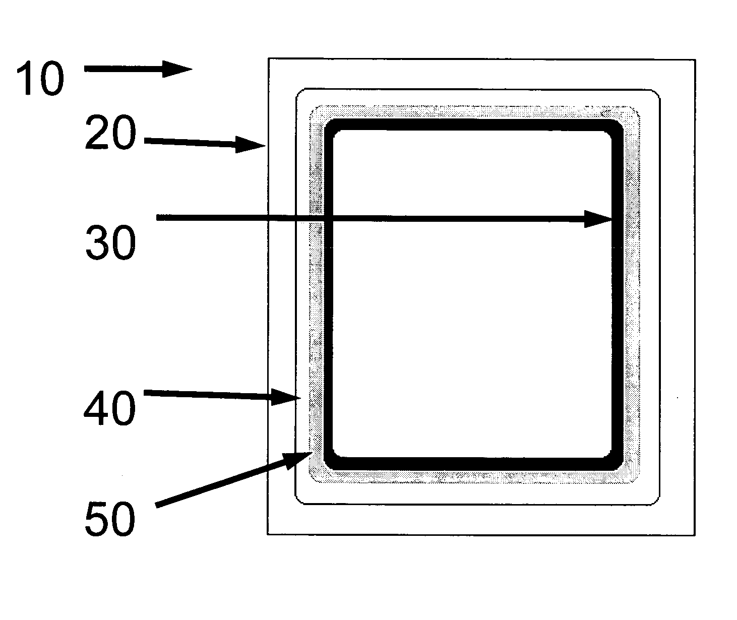
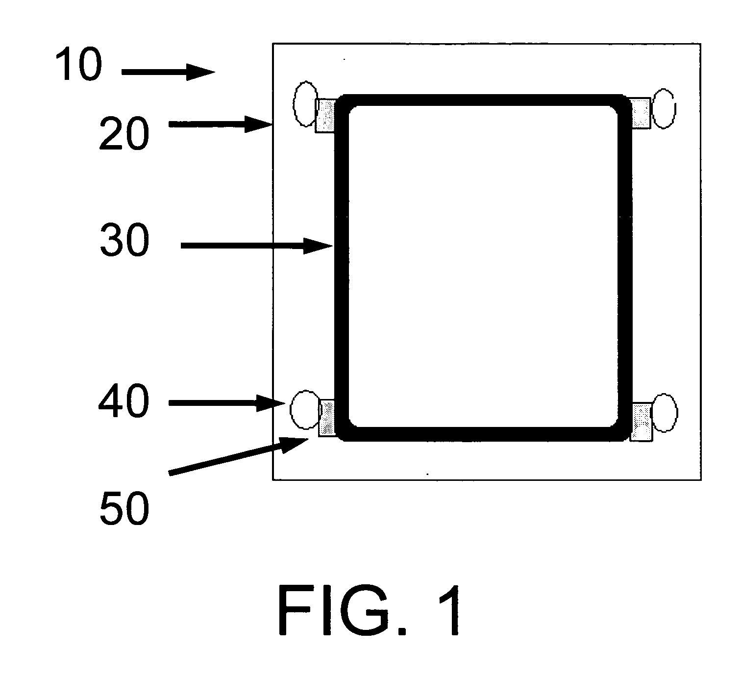
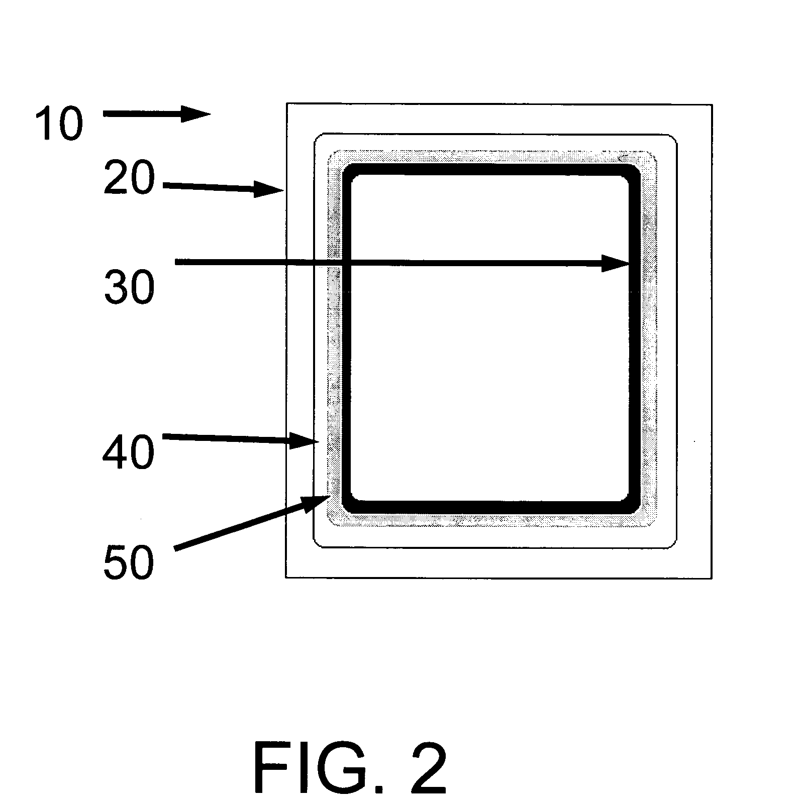
[0112]In a third example, a frit paste can be prepared for application to a substrate. Initially, a 2 wt. % binder solution can be prepared by dissolving a T-100 ethylcellulose binder, available from Hercules, Inc. (Wilmington, Del., USA) in TEXANOL®, an ester alcohol, available from Eastman Chemical Company (Kingsport, Tenn., USA). A frit paste can then be prepared by mixing the following components: 19.09 grams of the T-100 / TEXANOL solution prepared above, 55.33 grams of the glass powder prepared in Example 2, and 0.61 grams of an OC-60 wetting agent, available from Dexter Chemical, L.L.C. (Bronx, N.Y., USA). The resulting frit paste can be dispensed onto an Eagle borosilicate glass substrate (Corning Inc., Corning, N.Y., USA), in a square pattern. The applied frit can then be sintered to the Eagle substrate at 700° C. for approximately 2 hours in a nitrogen environment.

[0113]Additional frit paste can be applied at the four corners of t...


PUM

PropertyMeasurementUnit
Polymericaaaaaaaaaa
Coefficient of linear thermal expansionaaaaaaaaaa

Abstract

A glass package is disclosed comprising a first substrate and a second substrate, where the substrates are attached in at least two locations, at least one attachment comprising a frit, and at least one attachment comprising a polymeric adhesive and wherein the frit comprises a glass portion comprising: a base component comprising and at least one absorbing component. Also disclosed is a method of sealing a light emitting display device comprising providing a light emitting layer, a first substrate and a second substrate, where a frit is deposited between the substrates and a polymeric adhesive is deposited either between the substrates or around the edge of the device, and where the frit is sealed with a radiation source and the polymeric adhesive is cured.

Description

BACKGROUND OF THE INVENTION[0001]1. Field of the Invention[0002]The present invention relates to hermetically sealed glass packages that are suitable to protect thin film devices that are sensitive to the ambient environment.[0003]2. Technical Background[0004]Light emitting devices have been the subject of considerable research in recent years. Organic light emitting devices (OLED) are of particular interest because of their use and potential use in ac wide variety of electroluminescent devices. A single OLED, for example, can be used in a discrete light emitting device, or an array of OLEDs can be used in lighting applications or flat-panel display applications, such as OLED displays. Traditional OLED displays are known as being very bright and having a good color contrast and wide viewing angle. However, traditional OLED displays and in particular the electrodes and organic layers located therein are susceptible to degradation resulting from interaction with oxygen and moisture le...

Claims


Application Information

Patent Timeline
IPC IPC(8): H05B33/04H05B33/10
CPCB32B17/06C03C3/066C03C3/091C03C3/093C03C3/21H01L51/5237C03C8/08C03C8/24C03C27/06C03C27/10C03C8/04H10K59/8722H05B33/04H10K50/8426
Inventor LOGUNOV, STEPHAN LVOVICHREDDY, KAMJULA PATTABHIRAMI
Owner CORNING INC
Why Eureka
Try Eureka