Hydrogen based energy storage apparatus and method

a technology of energy storage apparatus and hydrogen based energy, which is applied in the field of storage of energy, can solve problems such as reducing the transmission system's constriction, and achieve the effects of reducing transmission capacity, reducing the cost, and reducing the adverse effects of the transmission system

Inactive Publication Date: 2009-05-26
PLUG POWER
View PDF23 Cites 4 Cited by
  • Summary
  • Abstract
  • Description
  • Claims
  • Application Information

AI Technical Summary

Benefits of technology

[0009]In accordance with the invention, electric energy generated by a primary electric power source is transmitted to a specified location remote from a utility generating station where it is stored by using it to disassociate water into hydrogen and oxygen, which are stored for later conversion of at least the hydrogen into locally generated electricity in a hydrogen to electricity converter. The utility generated electricity is wheeled to the specified location, such as a user site, a substation, or on a distribution line during off-peak periods and the stored gases are used to produce the locally generated electricity during peak periods. Thus, the low cost power generated by the utility during low demand periods can be converted to higher value electric power during peak periods. In addition, the adverse effects of constriction on the transmission system are ameliorated by reducing the transmission capacity required during peak demand periods. This advantage is enhanced by wheeling the utility generated power during low demand periods to a plurality of distributed specified locations remote from the utility generating station. Also, by providing distributed generation using stored gas, the effects of transmission interruptions, such as for example by storms, are mitigated.

Problems solved by technology

In addition, the adverse effects of constriction on the transmission system are ameliorated by reducing the transmission capacity required during peak demand periods.

Method used


Image

  • Hydrogen based energy storage apparatus and method
  • Hydrogen based energy storage apparatus and method
  • Hydrogen based energy storage apparatus and method

Examples


Embodiment Construction

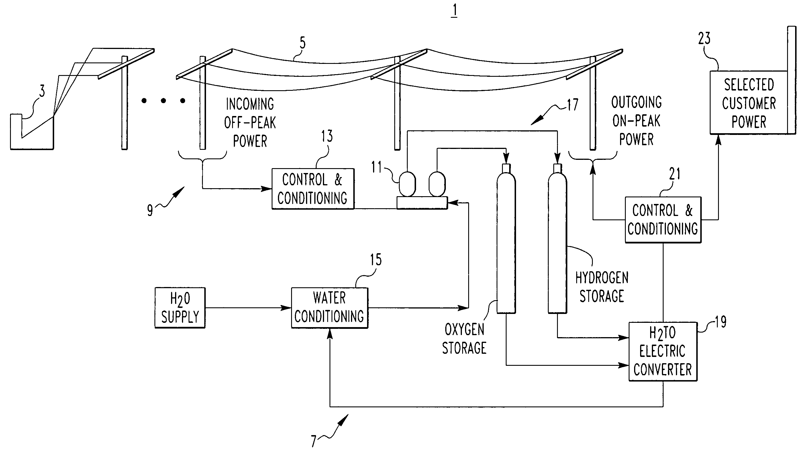
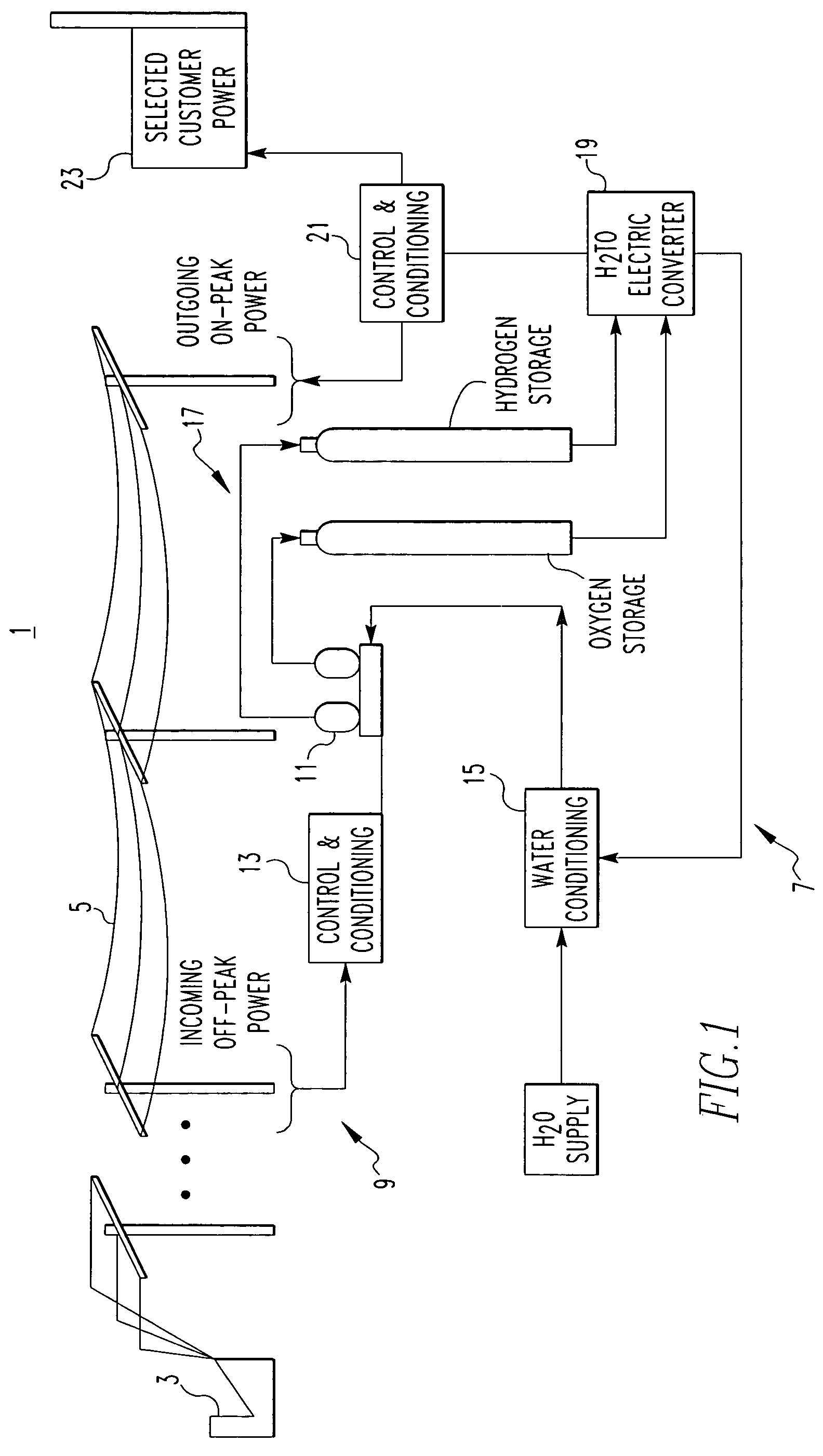
[0017]FIG. 1 illustrates an electric power system 1 in which a primary electric power source 3 such as a utility generating station provides electric power to a transmission system 5. The utility generating plant 3 can be a fossil-fueled plant, a nuclear plant, a hydroelectric plant or a renewable power source such as a wind generator or solar generator. The source of the primary power provided to the transmission system is not critical and there can be multiple primary power sources. In accordance with the invention, a hydrogen-based energy storage system 7 is located at a specified location 9 on the transmission system 5.

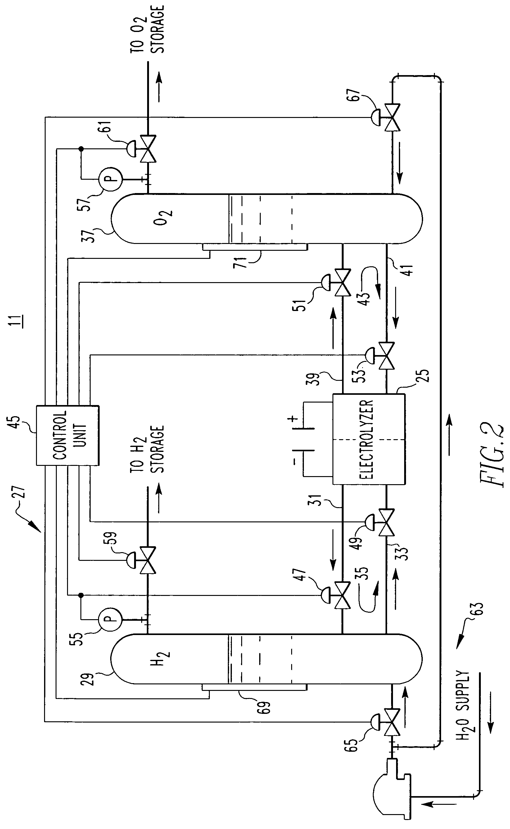
[0018]The hydrogen-based energy storage system 7 includes an electricity-to-hydrogen converter 11 energized by power provided from the transmission system 5 through an incoming power control and conditioning unit 13, which among other things, rectifies the multiphase transmission line power. The electricity-to-hydrogen converter 11 disassociates water provided thr...


PUM

PropertyMeasurementUnit
pressureaaaaaaaaaa
pressureaaaaaaaaaa
pressureaaaaaaaaaa

Abstract

Utility power is wheeled to distributed hydrogen energy storage systems during off peak periods where it is used in an electrolyzer to disassociate water into hydrogen and oxygen. The hydrogen at least is stored for use in a fuel cell or combustion engine driven generator to produce locally generated electricity during peak periods or power interruptions. Efficient electrolysis and gas storage are obtained by operating the electrolyzer at high pressures through two flow loops in which the hydrogen and oxygen produced in the electrolyzer pass to separate gas-water columns and force water into the electrolyzer. When the desired high pressure is reached, the gases are bled off into a series of storage tanks.

Description

[0001]This application is a divisional of application Ser. No. 10 / 091,308, now U.S. Pat. No. 6,787,258, filed Mar. 5, 2002.BACKGROUND OF THE INVENTION[0002]1. Field of the Invention[0003]This invention relates to the storage of energy for future use, and more particularly, to apparatus and a method for converting electrical energy during off-peak periods of low demand to hydrogen and oxygen that are stored for later conversion back into electrical energy during peak periods of high demand. It also relates to such a system and method that operates at self generated high pressure for efficient energy conversion and storage of the gases.[0004]2. Background Information[0005]Electric utilities have large installed capacity to met peak demand and the required safety margin. Most of the time, especially at night and weekends, only a fraction of that capacity is required to meet nominal demand. In fact, some of the peaking units operate only a few hours a year. In addition, utilities purcha...

Claims


Application Information

Patent Timeline
Patent Type & Authority Patents(United States)
IPC IPC(8): C25C1/02C25B15/00H01M8/00H01M8/18H01M8/06
CPCH01M8/0656Y02E60/50
Inventor PRERAD, VLADIMIR
Owner PLUG POWER
Why Eureka
Try Eureka