Efficient and accurate alignment of stereoscopic displays

a stereoscopic display and accurate technology, applied in the field of stereoscopic three-dimensional display system, can solve the problems of unsafe operation of remotely controlled equipment using the display system, inefficiency of the application employing the display, visual fatigue, image distortion,

Active Publication Date: 2009-05-26
THE BOEING CO
View PDF11 Cites 37 Cited by
  • Summary
  • Abstract
  • Description
  • Claims
  • Application Information

AI Technical Summary

Benefits of technology

[0020]Such and apparatus and method can make it possible for technicians with less expertise to check and correct binocular display alignment before use of the applicable sterescopic display by following a related inventive method of opertion. Thus, embodiments of the invention provide a built-in test system for the alignment aspect of the dual-screen stereoscopic three-dimensional display unit.

Problems solved by technology

Mismatch between display geometry and camera geometry can cause operational inefficiency of the application employing the display, visual fatigue, and image distortion, among other negative effects.
Such mismatch can result in errors and unsafe operation of remotely-controlled equipment employing the display system.
Operators will suffer visual fatigue, discomfort, and / or headaches, limiting the allowable operational period.
Such displays present distorted and / or mis-aligned images.
Such systems can suffer from operator complaints which may ultimately lead to abandonment of the poorly performing stereoscopic three-dimensional display system.
However, correct binocular alignment of a dual-image stereoscopic three-dimensional display can be complicated and prone to error.
In addition, proper alignment of such displays typically requires special expertise not always available.
Because of these and other factors, it is usually not practical to employ a single dual-channel stereoscopic three-dimensional display applied to different imaging geometries (e.g. different input cameras), since this would require time-consuming and difficult re-alignment of the display to match inputs from a different imaging geometry.
Currently available stereoscopic three-dimensional displays are therefore limited, practically, to use with only one type of input geometry, since it is often too difficult to change back and forth between different input imaging configurations.
Current stereoscopic three-dimensional displays do not provide assistance in or accommodate the need for alignment of left and right display images to correctly match imaging system geometry (e.g., camera convergence and alignment).
When imaging geometry is complex, due to camera convergence, and left and right display-channel components are viewed through refractive and reflective optical elements, the process of correct alignment is difficult and requires expertise not always available.
Some auto-convergence systems and test patterns have been previously developed for 3-tube CRT video projectors in the previous decades for matching up the red, green, and blue projected images, however, such techniques are not directly applicable to the alignment of stereoscopic three-dimensional displays.
In addition, current stereoscopic three-dimensional systems do not provide the means for an operator to check and / or adjust the display alignments required for different camera configurations.

Method used


Image

  • Efficient and accurate alignment of stereoscopic displays
  • Efficient and accurate alignment of stereoscopic displays
  • Efficient and accurate alignment of stereoscopic displays

Examples


Embodiment Construction

[0034]1. Overview

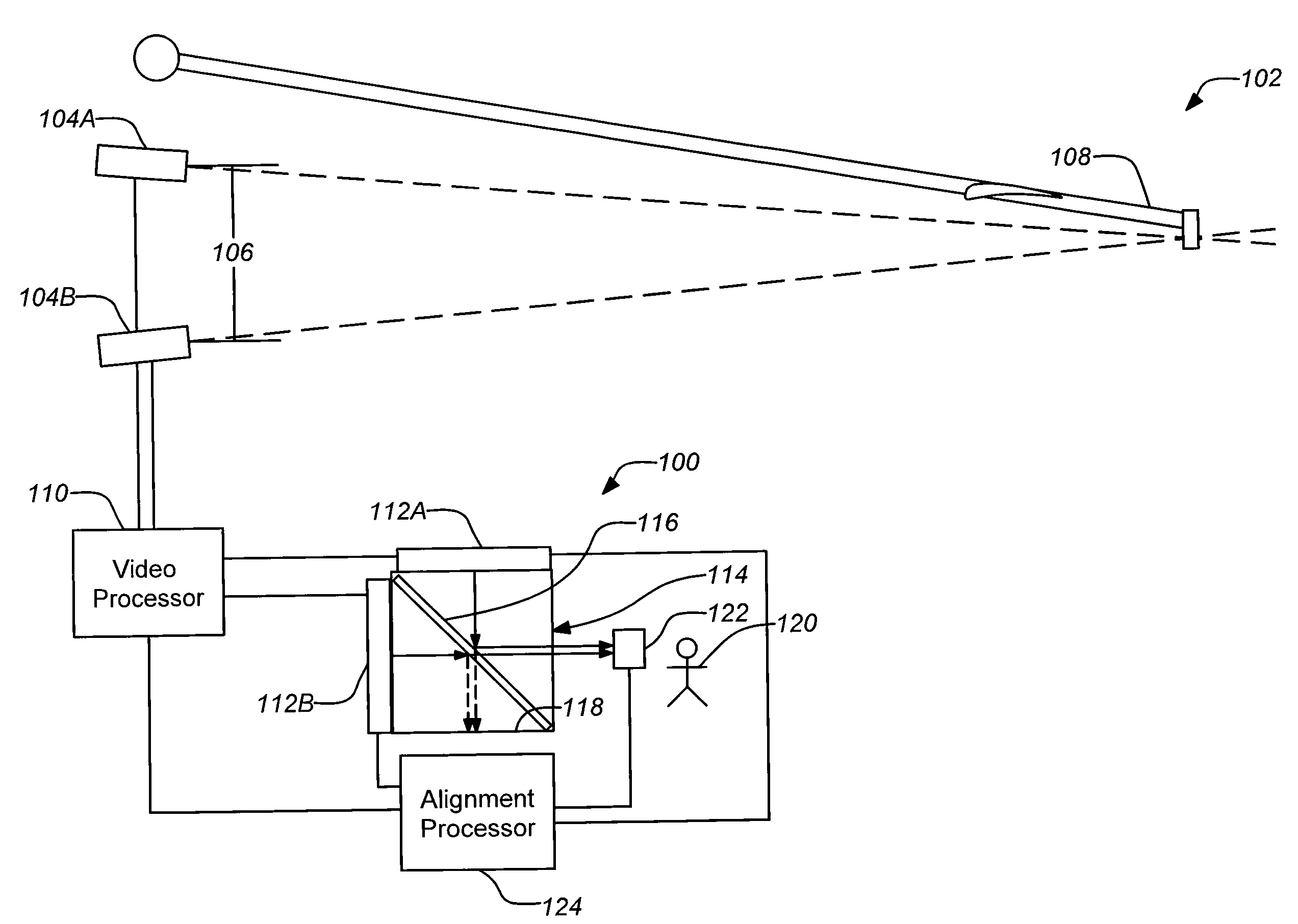
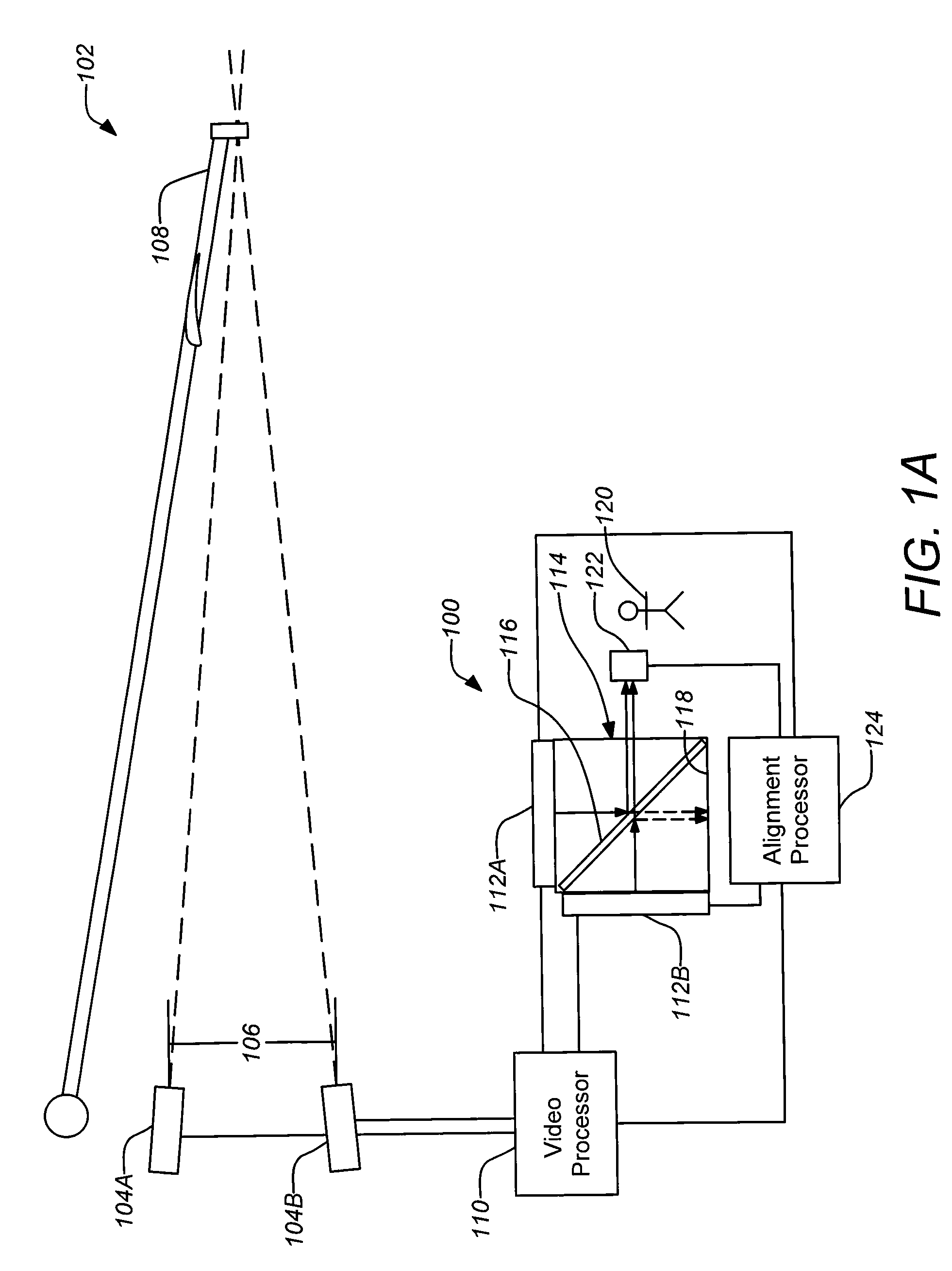
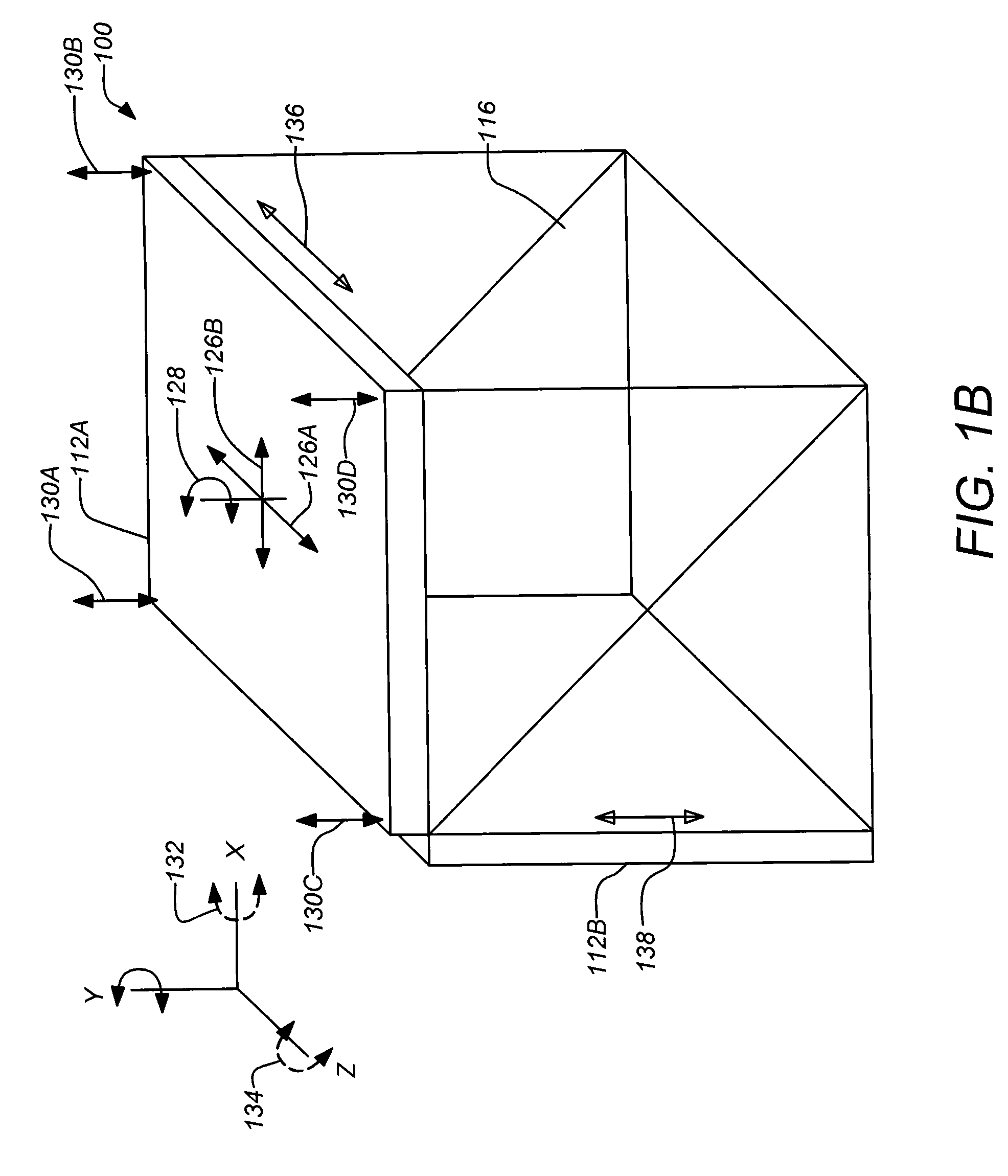
[0035]Embodiments of the present invention are directed to a method and apparatus that provides assistance to an operator (e.g. a technician) in aligning the left and right image channels a two-image stereoscopic three-dimensional display by showing left and right alignment patterns on the left and right image screens, pre-computed for any given input imaging geometry, such that the operator has simply to visually superimpose the left and right test patterns by moving the display elements using display positioning equipment and / or software. This ensures that the stereoscopic three-dimensional display geometry matches the three-dimensional camera imaging geometry in order to produce a minimally-distorted visual depth perception of objects in space. An additional enhancement may be achieved by having these display adjustments performed automatically without requiring visual feedback to an operator in the loop. Such precision alignment can be essential for efficient an...


PUM


Abstract

A method and apparatus for aligning the left and right image channels a two-image stereoscopic three-dimensional display is disclosed. A left and right alignment pattern may be shown on the left-eye and right-eye image screens, respectively, pre-computed for any given input imaging geometry. The operator (or alignment processor) then adjust the displays to converge the superimposed left-eye and right-eye test patterns by moving the display elements using display positioning equipment and / or software. This ensures that the stereoscopic three-dimensional display geometry matches the three-dimensional camera imaging geometry in order to produce a minimally-distorted visual depth perception of objects in space. Such precision alignment can be essential for efficient and safe telerobotic operation applications, as in the case of remote aerial refueling operations, for example.

Description

BACKGROUND OF THE INVENTION[0001]1. Field of the Invention[0002]This invention relates to stereoscopic three-dimensional displays. Particularly, this invention relates to systems and methods for the alignment of stereoscopic three-dimensional displays such as may be employed in aerospace applications.[0003]2. Description of the Related Art[0004]Stereoscopic three-dimensional displays function through the synchronized presentation of different images to the left and right eyes of a user. In principle, the images are differentiated to simulate the parallax that would naturally occur between two eyes of a viewer if actually present at the camera location. Thus, the brain can process the differentiated images normally to provide depth perception to the user. Alignment of the separate images at the point where they are received by the separate eyes is an important factor in the development of any stereoscopic three-dimensional display system.[0005]Mismatch between display geometry and ca...

Claims


Application Information

Patent Timeline
Patent Type & Authority Patents(United States)
IPC IPC(8): G01J4/00
CPCH04N13/0443H04N13/0497H04N13/346H04N13/398
Inventor HEWITT, GORDON S.MERRITT, JOHN O.
Owner THE BOEING CO
Why Eureka
Try Eureka