Dynamic routing in packet-switching multi-layer communications networks

a multi-layer communication and dynamic routing technology, applied in the field of packet-switching communications networks, can solve the problems of affecting network performance, current backbone network architecture, and affecting network performance, and achieve the effect of improving performan

Inactive Publication Date: 2009-05-26
TELEFON AB LM ERICSSON (PUBL)
View PDF11 Cites 24 Cited by
  • Summary
  • Abstract
  • Description
  • Claims
  • Application Information

AI Technical Summary

Benefits of technology

[0027]Aim of the present invention is to provide a method and a system for exploiting available network resources so as to improve network performance.
[0037]A multi-layer network managed according to the invention as claimed achieves a better performance in comparison with the state of the art, with particular referral to blocking probability and total refused bandwidth.

Problems solved by technology

In recent years, the fast growing of datacom networks and the large and ever-increasing amount of services made available to the users over such networks, particularly over the Internet, have led to a remarkable growth of traffic which is heavily affecting network performance.
As a matter of fact, current architectures of backbone networks, which were originally designed to support telephone traffic, are inadequate to support huge volumes of Internet data traffic and, ideally, should be replaced by technically advanced, state of the art hardware networks providing sufficient speed and bandwidth to cope with today's and tomorrow's data traffic needs.
Unfortunately, cost is a major issue which is slowing down, if not preventing, the hardware modernisation process: the common feeling is that investments would be too high with respect to expected revenues.
Unfortunately, such traditional multi-layer architectures suffer from the lowest common denominator effect where one layer can limit the scalability of the entire network and they have proven to be not only also cost ineffective but also hard and slow to scale for very large volumes of traffic.
Both the IP / MPLS and RWA engineering approaches, however, have not proven to be fully satisfactory, in that optimisation in a layer is still too often affected by critical loads or different situations occurring on the other layer.

Method used


Image

  • Dynamic routing in packet-switching multi-layer communications networks
  • Dynamic routing in packet-switching multi-layer communications networks
  • Dynamic routing in packet-switching multi-layer communications networks

Examples


Embodiment Construction

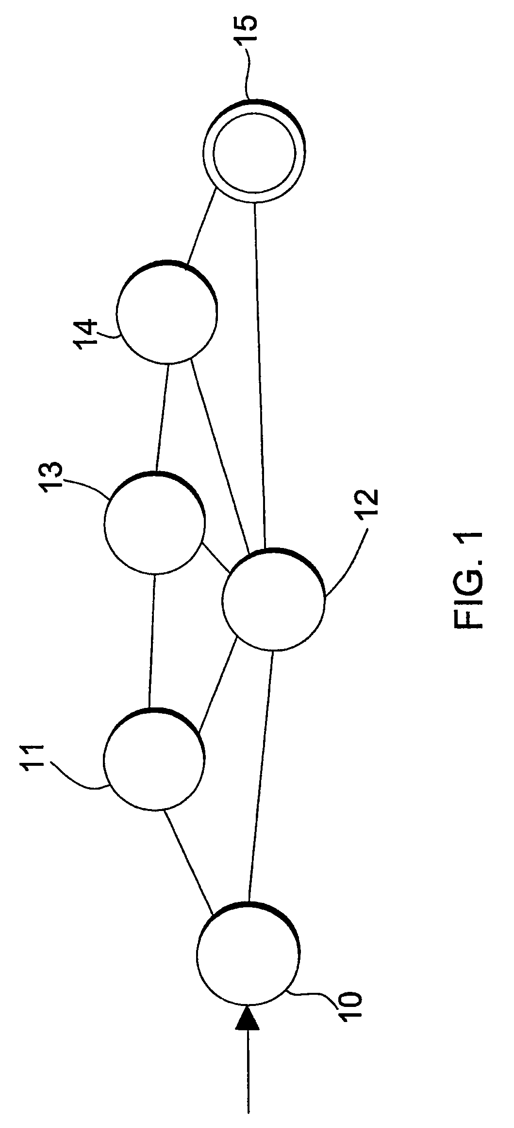
[0045]FIG. 1 is a schematic view showing an exemplary communications network comprising a plurality of nodes 10 to 15 and an exemplary data packet which is to travel from start node 10 to end node 15.

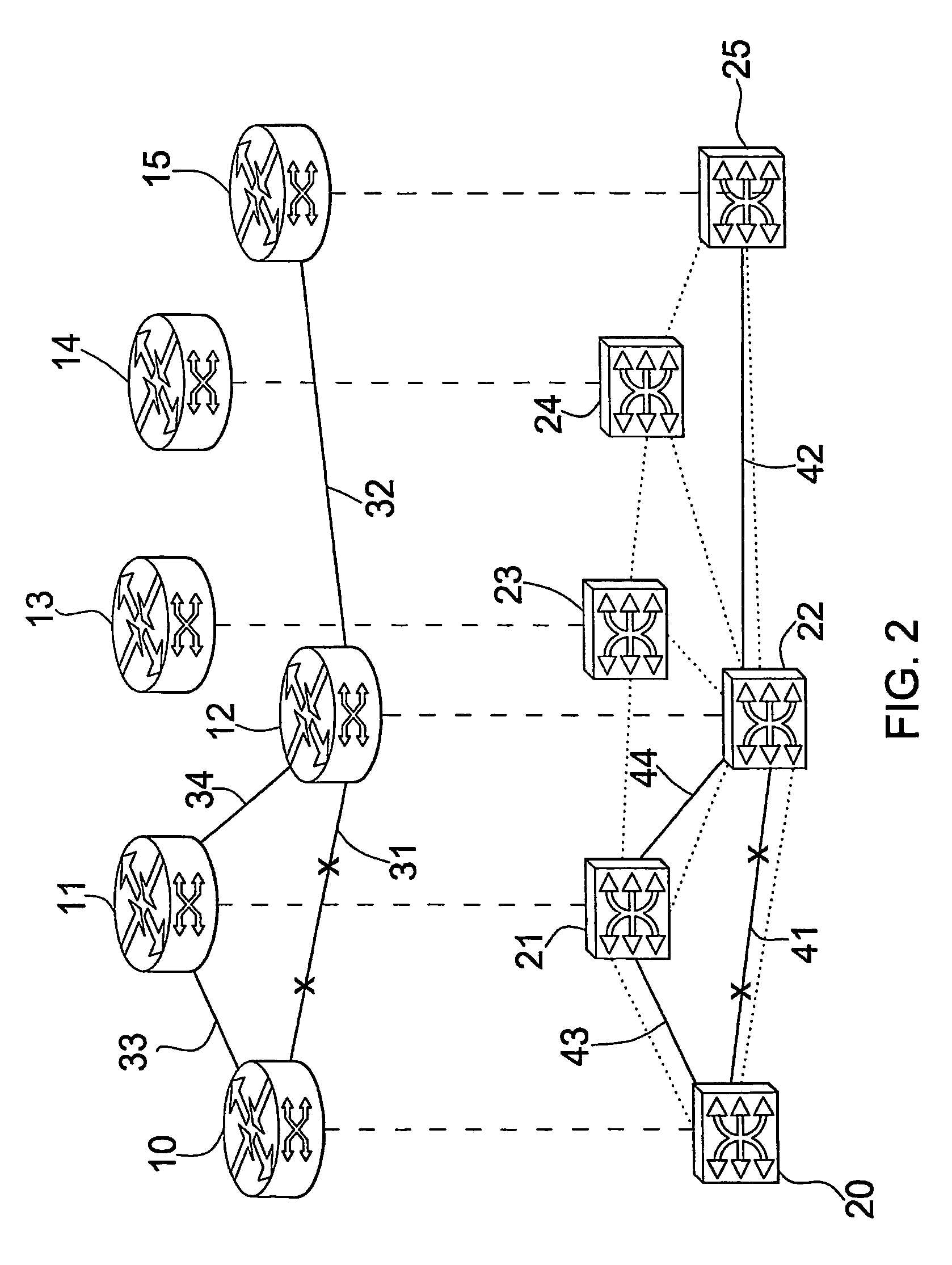
[0046]The nodes are treated in two different levels or domains: a logical or routing level and a physical level.

[0047]Each node in the logical domain is associated to a router, hereinafter indicated with the same reference number as the corresponding node, which performs the necessary actions to route an incoming data packet to a next node along a path leading to the final packet destination address.

[0048]Similarly, each node in the physical domain is associated to a switch, which performs the necessary actions to physically transfer an incoming data packet to the next switch through a selected physical transport means.

[0049]A generic connection between two nodes, namely a source node and a destination node, as treated in the logical domain, is referred to as a logical link, while the a...


PUM


Abstract

A method is provided for routing data packets across a multi-layer network which includes a plurality of nodes, a logical level provided with a plurality of logical links and a physical level provided with a plurality of physical links, each of the logical links corresponding to at least one of the physical links, the method comprising the steps of assigning a weight to each logical link with respect to a first critical constraint in the logical level, refining the weight assigned to each logical link with respect to a second critical constraint in the physical level and, based on the weights assigned to each link, computing a path at the logical level connecting a start node to an end node for the transport of the data packets.

Description

TECHNICAL FIELD[0001]The present invention relates to packet-switching communications networks and, more particularly, to routing strategies in multi-layer networks.BACKGROUND ART[0002]In recent years, the fast growing of datacom networks and the large and ever-increasing amount of services made available to the users over such networks, particularly over the Internet, have led to a remarkable growth of traffic which is heavily affecting network performance.[0003]As a matter of fact, current architectures of backbone networks, which were originally designed to support telephone traffic, are inadequate to support huge volumes of Internet data traffic and, ideally, should be replaced by technically advanced, state of the art hardware networks providing sufficient speed and bandwidth to cope with today's and tomorrow's data traffic needs.[0004]Unfortunately, cost is a major issue which is slowing down, if not preventing, the hardware modernisation process: the common feeling is that in...

Claims


Application Information

Patent Timeline
Patent Type & Authority Patents(United States)
IPC IPC(8): H04J3/22H04J14/02H04L12/46H04L45/02H04L45/125H04L45/50
CPCH04L29/06H04L45/02H04L45/124H04L45/125H04L45/50H04L45/62H04L45/64H04L47/10H04L47/125H04L69/32H04L9/40H04L69/321
Inventor IOVANNA, PAOLASABELLA, ROBERTOTOU, PIETROORIOLO, GIANPAOLO
Owner TELEFON AB LM ERICSSON (PUBL)
Why Eureka
Try Eureka