Milking apparatus and method with transversely stretched membranes

a transverse stretch and membrane technology, applied in the field of milking apparatuses, can solve the problems of complex forces, little thought given to the precise effect of generated forces, complex forces, etc., and achieve the effect of increasing the control of pressure exerted

Active Publication Date: 2009-06-02
MILKRITE INTERPULS LTD
View PDF24 Cites 5 Cited by
  • Summary
  • Abstract
  • Description
  • Claims
  • Application Information

AI Technical Summary

Benefits of technology

[0018]The resilient membranes may be put under axial tension (i.e. tension in the first direction), as well as transverse tension, if it is found that there needs to be a greater pressure on the teat end than on the part of the teat remote from the end. Each membrane can therefore effectively be tuned to the shape of a teat. Such tuning allows improved control over the pressures (forces) exerted on the teat and therefore may be used to ensure that teat health is kept to an optimum.
[0021]Normally, the space between the membranes will be subject to suction, in a way similar to the interior of known liners. However, it is possible in addition to provide an over-pressure between the outside of the membranes and the interior of the body into which the membranes are received, since it is believed that such a positive pressure is of beneficial effect. Where a common region surrounding the membranes is used as described above, the same pressure can easily be applied to the outside of all membranes. Furthermore, it is possible to use only over pressure without suction being applied to the interior of the liner.
[0024]In a development of the present invention, the apparatus is adapted to reduce the forces experienced by parts of the animal adjacent the opening in the outer body caused by the pressure difference between the space for the teat and the region outside the membranes. In particular, this development aims to mimic more closely the forces a teat would experience from a suckling calf.
[0025]Thus, the membranes are preferably divided into two or more sub-membranes so that the membranes form a set of chambers surrounding said space, each chamber having one or more sub-membranes facing said space. The pressure generating device may be arranged to provide an independently controllable pressure difference for each chamber. The chambers may therefore be independently operable, e.g. in a user-determined sequence. This therefore allows different parts of the membrane surface to press against the teat at different times.

Problems solved by technology

However, in all the time that such milking apparatuses have been used, little thought seems to have been given to the precise effect of the forces that are generated.
However, the forces are complicated as both the liner and the teat are resilient.
The forces are therefore complex.
As a result of this, the tissue of the teat can fill excessively with fluid, since the suction forces are around −40 kPa relative to atmospheric pressure.
If the tension is large, the forces generated at the teat end may damage the teat.
However, if the tension is low, to avoid such damage, then the pressure applied on the teat away from the teat end (along the teat ‘barrel’) is small.

Method used


Image

  • Milking apparatus and method with transversely stretched membranes
  • Milking apparatus and method with transversely stretched membranes
  • Milking apparatus and method with transversely stretched membranes

Examples


first embodiment

[0045]Again, as in the first embodiment, the body 46 has an opening 54 into which the teat is received so that the teat lies within space 48. An outlet 56 is provided at the end of the body 46 remote from the opening 54 to which suction is applied.

[0046]Note that in this second embodiment the structure defined by the membranes 40, 42, 44 has an upper flange 58 which fits over the top of the body 46, and the suction outlet 56 is integral with the membranes 40, 44, 44 and has a further flange 60 fitting over the bottom of the body 46. Thus, in such arrangement it is possible for the membranes 40, 42, 44 to be under longitudinal tension (i.e. in the axial direction of the teat) as well as under transverse tension. Moreover, in the second embodiment, there is an inlet 62 communicating with the spaces 64 between the membranes 40, 42, 44 and the body 46, to enable an over-pressure to be applied to the outsides of the membranes 40, 42, 44. Indeed, it may be possible for this embodiment to ...

second embodiment

[0047]Again, FIGS. 4A and 4B illustrate the second embodiment when a teat 66 is inserted into the structure shown in FIGS. 3A and 3B, suction applied to the outlet 56, and an over-pressure applied to the inlet 62. The membranes, 40, 42, 44 close around the teat 66, closing the space 48. Thus, again, pressure is applied to the teat not only at the teat end, but along the barrel of the teat.

[0048]Thus, by putting the membranes under transverse tension, the pressures applied to the teat can be controlled so that pressure is applied over substantially the whole length of that part of the teat within the apparatus, thereby achieving an improved milking action, without exerting excessive forces on the end of the teat.

[0049]FIGS. 5A to 5D illustrate a third embodiment of the invention. In this embodiment, the liner is attached within the outer body 70 in such a way that there is no contact between the inside side surfaces of the outer body 70 and the liner. Similar to FIGS. 3 and 4, FIG. 5...

fifth embodiment

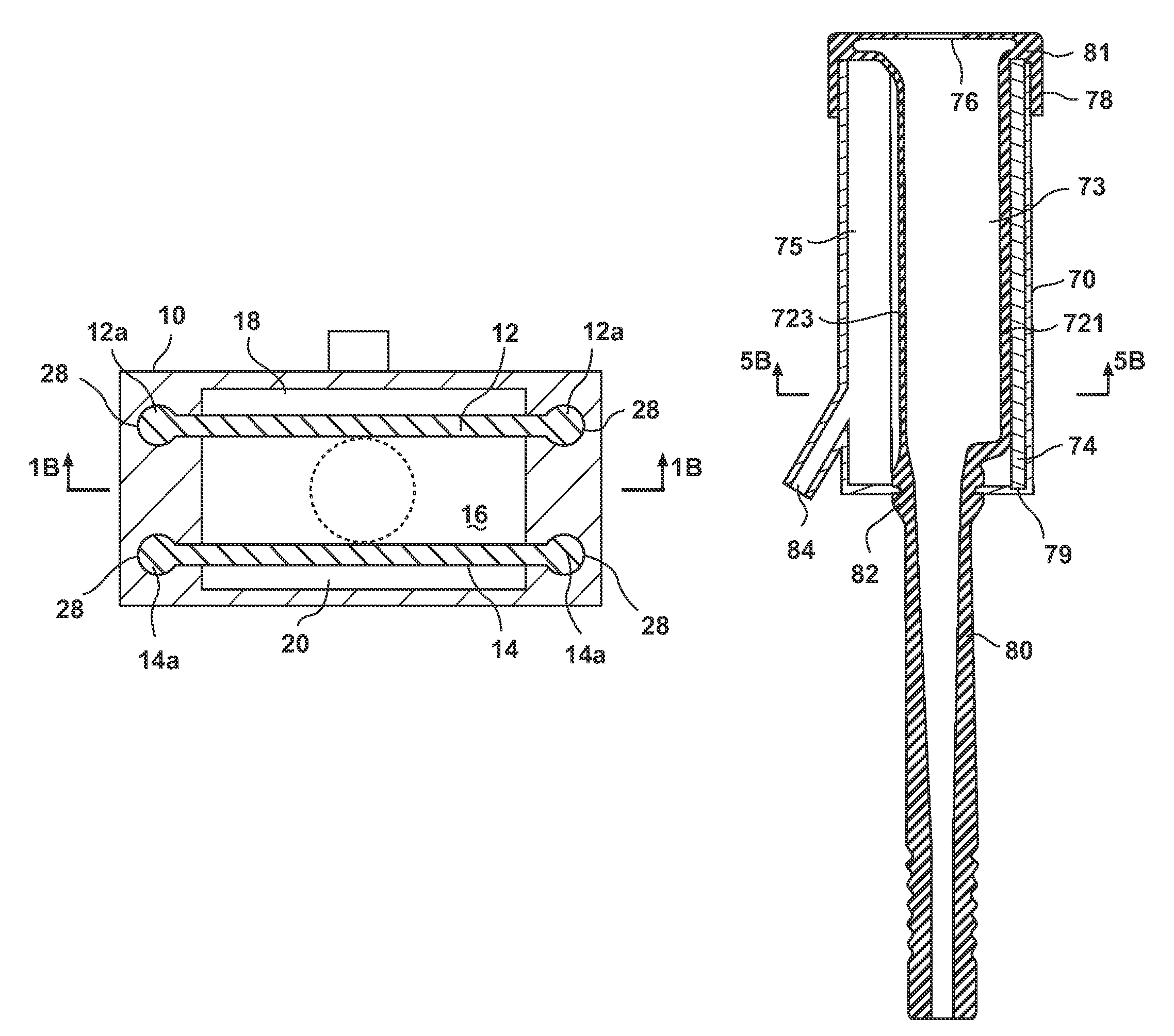
[0055]FIGS. 7A to 7C show the invention, which resembles the embodiment shown in FIGS. 5A to 5D. The same reference numbers are used for corresponding parts, and these are not described again. FIG. 7C shows a different type of attachment at the top (upper) end of rod 74. A protruding jaw 71 extends radially inwards from the interior wall of the outer body 70 and captures the rod 74, thereby holding it securely in place.


PUM


Abstract

Apparatus for removing milk from a teat of an animal comprising an outer body having an opening into which the teat is insertable into a space defined by two or more resilient membranes. A pressure difference is applied between the space between the resilient membranes and a region outside the membranes to cause the membranes to ball on to the teat, thereby massaging it to extract milk. To avoid exerting excessive force on the end of the teat yet retain a useful massage pressure, the resilient membranes are under tension in a direction transverse to the direction of teat insertion before the provision of any pressure difference (before the insertion of the teat).

Description

CROSS-REFERENCE TO RELATED APPLICATION[0001]This application claims the benefit of GB Application No. 0423132.0, filed Oct. 18, 2004, which is incorporated herein in its entirety.BACKGROUND OF THE INVENTION[0002]1. Field of the Invention[0003]The present invention relates to a milking apparatus, i.e. an apparatus for removing milk from a teat of an animal. It also relates to a method of use of such an apparatus.[0004]2. Summary of the Prior Art[0005]In a conventional milking apparatus, a cylindrical liner of resilient material is housed within an outer body, and the liner is tensioned along the axis of the cylinder. The teat of the animal is then inserted through an opening in the body into the cylindrical liner, and then suction is applied to another opening in the body, at the other end of the cylindrical liner to that in which the teat is inserted, to create a partial vacuum. This causes the liner to contract around the teat, and so causes milk to be expressed from the teat. Beca...

Claims


Application Information

Patent Timeline
Patent Type & Authority Patents(United States)
IPC IPC(8): A01J5/04A01J3/00A01J5/08
CPCA01J5/08
Inventor BOAST, DAVID
Owner MILKRITE INTERPULS LTD
Why Eureka
Try Eureka