[0012]The support structure is not a fixed part of the outer body, so in other words may be a discrete component of the apparatus and adapted to be removable from the outer body. By providing such a separate support structure onto which the membranes may be mounted e.g. before they are inserted into the outer body, it is possible to design a support structure that is easy to manipulate and which allows the membranes to be placed under transverse tension more easily than is the case for the apparatus of the prior art. Note, however, that the present invention does not exclude the possibility that the support structure is positioned within the outer body before the membranes are mounted thereon.
[0013]Furthermore, the use of a support structure allows the milking apparatus to be assembled using a standard outer body component, which does not need to be adapted to hold the membranes of the liner under transverse tension.
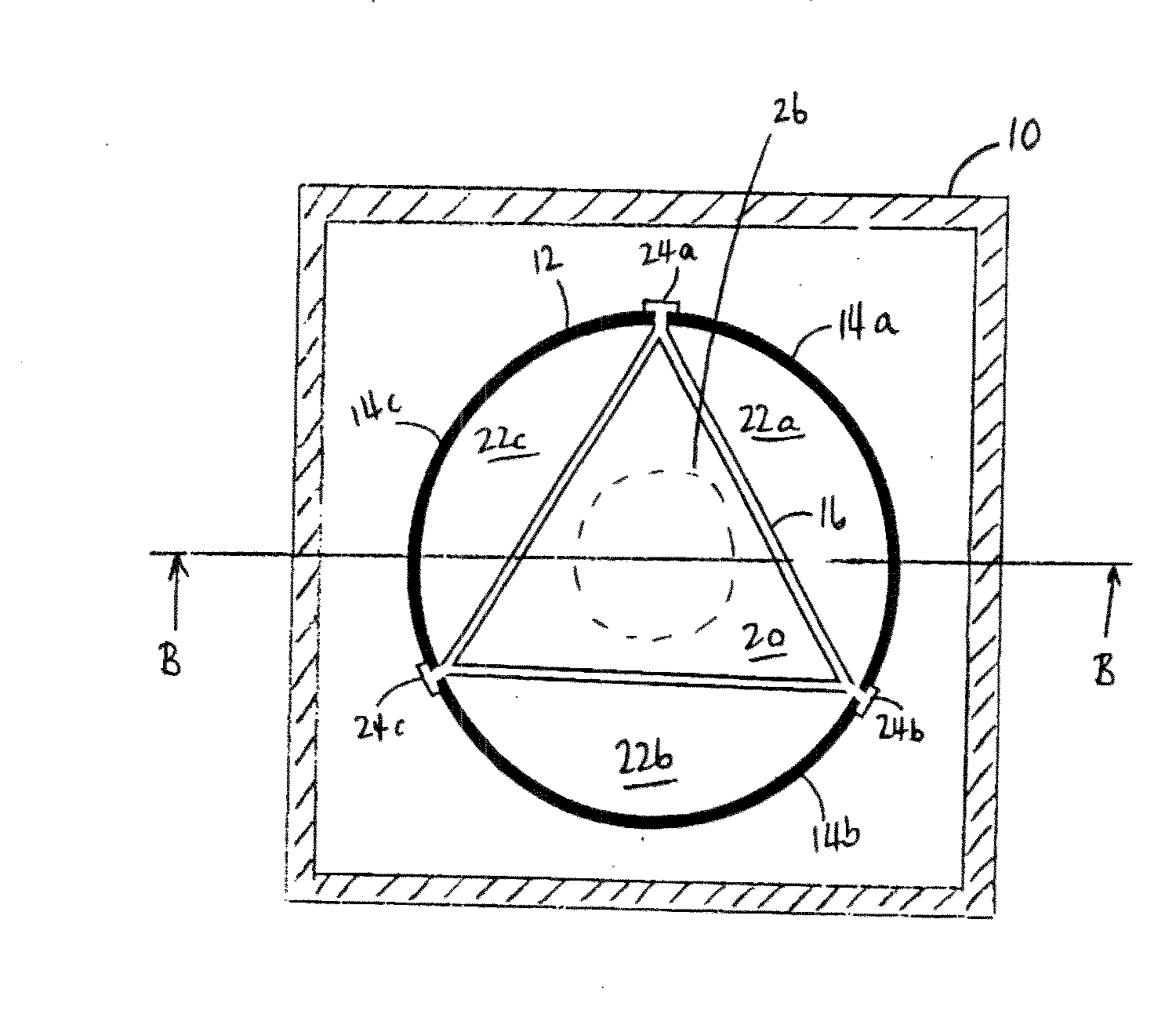
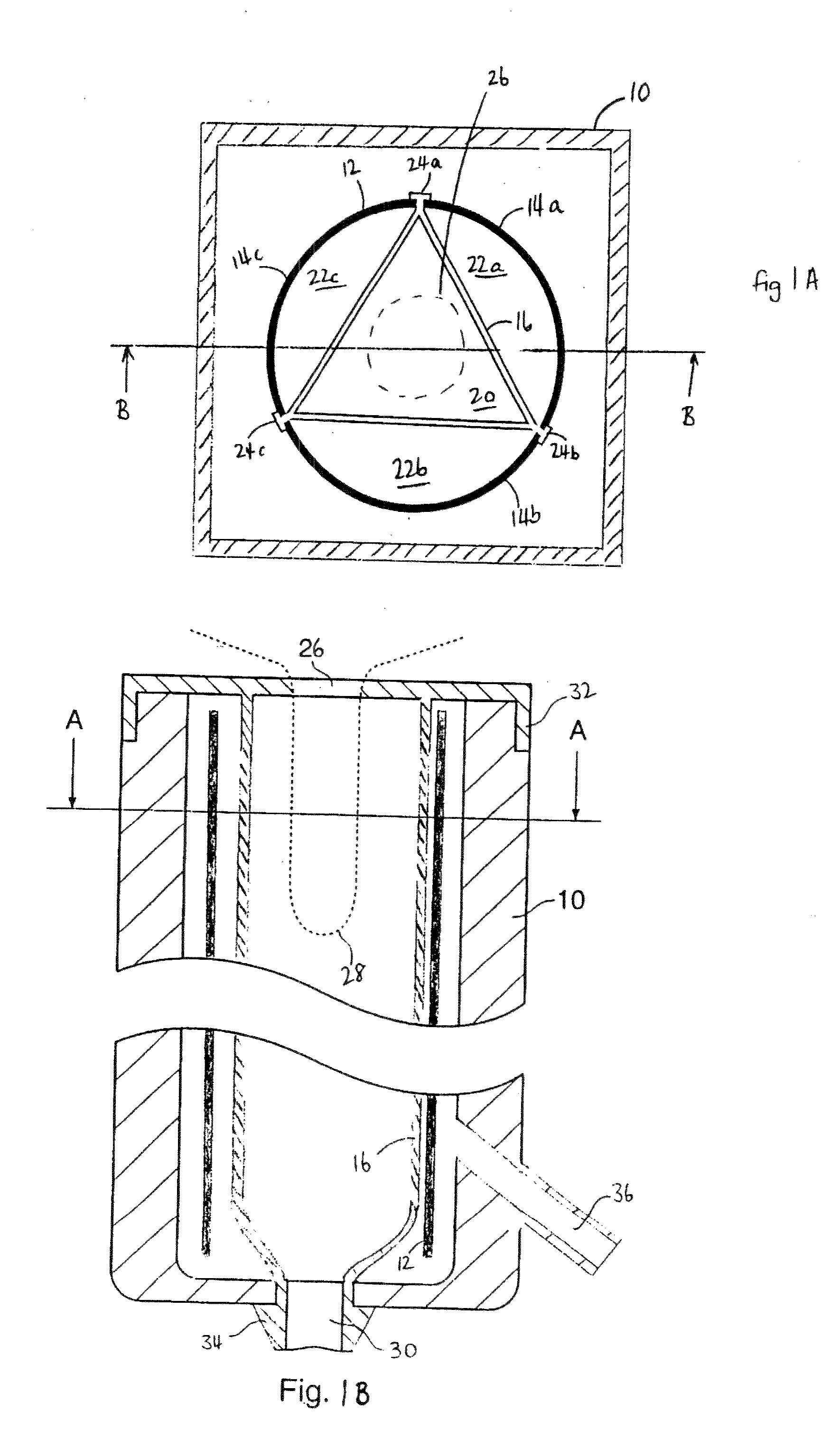
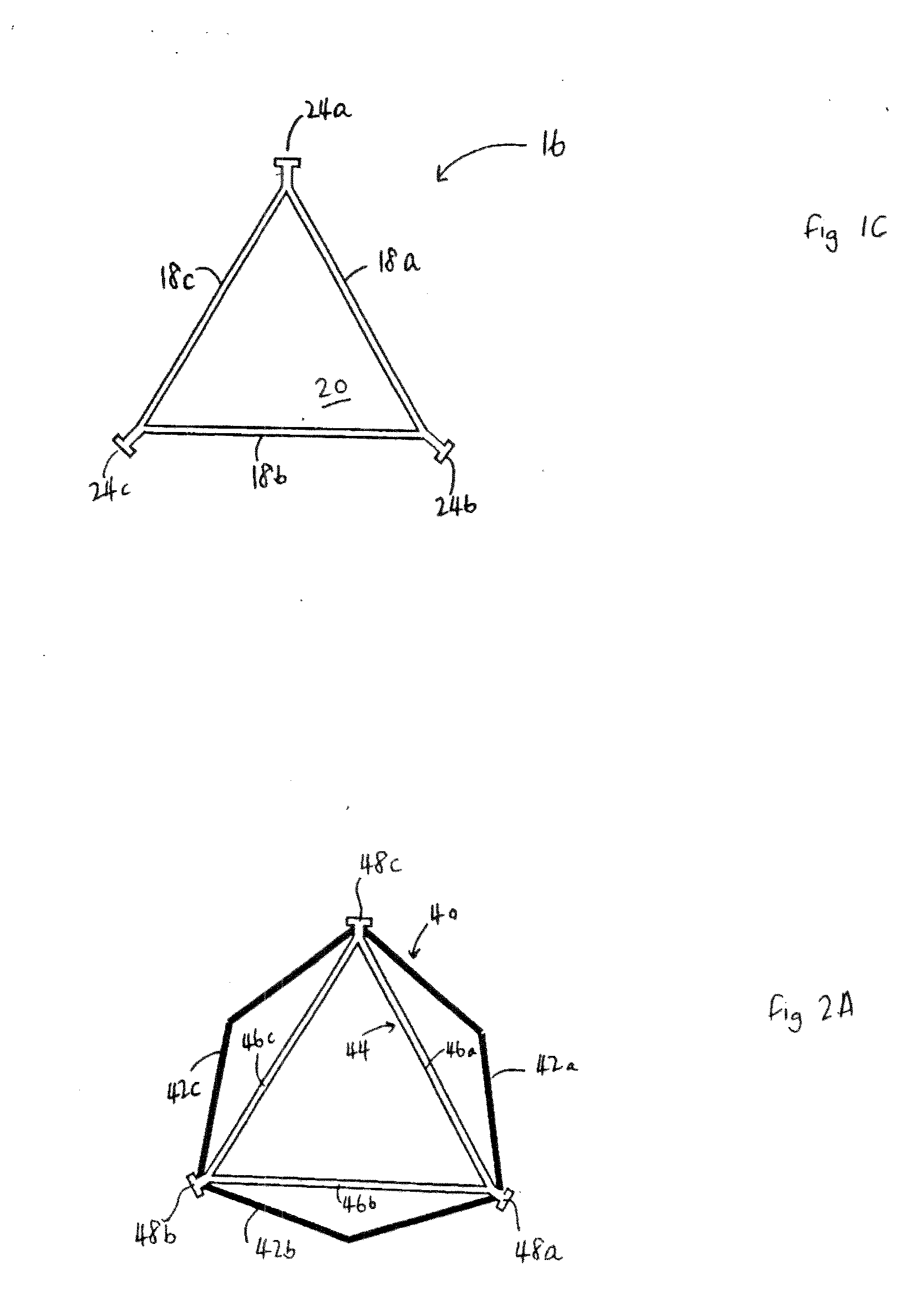
[0039]Accordingly, the present invention provides a support structure which holds the membranes of the liner under transverse tension. As will be understood from the discussion above, it may be preferable that the support structure has a first tensioning element having two spaced-apart attachment points and a second tensioning element having two spaced apart attachment point. The first membrane may be attached or attachable to the first tensioning element of the support structure at the two spaced apart attachment points so that the first membrane is under tension in a direction transverse to the first direction. Similarly, the second membrane may be attached to the second tensioning element of the support structure at the two spaced-apart attachment points so that the second membrane is under tension in a direction transverse to the first direction when there is the same pressure across the membranes. This tensioning effect may be achieved by making the relaxed distance between attachment points on, for example, the first tensioning element of the support structure greater than the relaxed length of the first membrane which is to span these points and similarly for the second membrane and corresponding tensioning element. The attachment points of the support structure are spaced radially inward from the outer body.
[0042]The section between the two attachment points on each tensioning element may be either straight or curved, or have a peak. When curved or peaked elements are used, attachment of the membranes becomes easier, since the elements are capable of being flexed more easily than straight elements in order to bring the distance between the attachment points closer to the relaxed length of the membrane. Furthermore, using curved or peaked tensioning elements, particularly peaked elements, it is easier to tension the membranes at the low transverse stress levels preferred for milking, since the elements will tend to bend to relieve some of the tension in the membrane.
[0047]The resilient membranes may be put under axial tension (i.e. tension in the first direction), as well as transverse tension, in order to tune the membranes more effectively to the shape of the teat. In this case, it may be useful for the level of axial tension to be adjustable. Such tuning allows improved control over the pressures (forces) exerted on the teat and therefore may be used to ensure effective milking action, while optimizing teat health.
[0051]Normally, the space between the membranes will be subject to suction, in a way similar to the interior of known liners, while the region between the outside of the membranes and the interior of the body into which the membranes are received is periodically brought to
atmospheric pressure in order for the liner to close around the teat, thus providing temporary relief from the suction forces and reducing teat congestion. However, it is possible instead to provide a periodic
overpressure to the region between the membranes and the outer body, since it is believed that such a
positive pressure is of beneficial effect, as it matches the
internal pressure of the teat more closely. Furthermore, it is possible to use only over pressure without suction being applied to the interior of the liner.

