Modular pilot assembly with self-contained stripper and method for metal forming dies

Active Publication Date: 2013-07-04
STANDARD LIFTERS INC
View PDF8 Cites 17 Cited by
  • Summary
  • Abstract
  • Description
  • Claims
  • Application Information

AI Technical Summary

Benefits of technology

[0014]Yet another aspect of the present invention is a method for making a multi-station progressive metal forming die having at least two mutually converging and diverging die members between which an elongate stock strip is shifted longitudinally to form parts from the stock strip, with the improvement of at least one modular pilot with self-contained stripper for precisely locating the stock strip in the die stations. The method includes forming a pilot sleeve for operable support on one of the die members, with a generally cylindrical shape having an outer end portion oriented toward the stock strip, and oppositely disposed inner end portion oriented away from the stock strip, and a central aperture extending through the outer and inner end portions. The method also includes forming the outer end portion of the pilot sleeve with a generally flat outer end oriented toward the stock strip, a generally recessed inner end oriented away from the stock strip, and an outer sidewall with at least one fastener relief therein having an arcuately shaped, radially inwardly curved relief sidewall that extends axially from the flat outer end to a generally flat arcuately shaped relief end surface facing toward the stock strip and spaced axially outwardly a predetermined distance from the recessed inner end, as well as at least one axially extending ejector pin aperture which opens through the flat outer end and into the recessed inner end. The method also includes forming the inner end portion of the pilot sleeve with a generally annularly shaped spring retainer collar, having an outer end oriented toward the stock strip, an inner end oriented away from the stock strip, and an outer sidewall with a diameter that is less than the diameter of the outer sidewall of the outer end portion of the pilot sleeve, thereby forming an annularly shaped spring groove adjacent the outer end of the spring retainer collar. The method also includes forming at least one rigid ejector pin with an inner end, and an outer end configured to protrude outwardly from the flat outer end of the outer end portion of the pilot sleeve when urged to an extended position to contact the stock strip, and to retract toward the pilot sleeve when urged to a retracted position. The method further includes inserting the ejector pin into the ejector pin aperture in the body portion of the pilot, such that the ejector pin is slidingly received and retained in the ejector pin aperture for longitudinal reciprocation therein between the extended and retracted positions. The method also includes selecting a spring member with a generally hollow interior, an outer end oriented toward the stock strip, and an opposite inner end oriented away from the stock strip. The method further includes positioning the hollow interior of the spring member onto and over the spring retainer collar on the inner end portion of the pilot sleeve, with the outer end of the spring member received in the spring groove, and abutting the inner end of the ejector pin, and the inner end of the spring member protruding inwardly away from the outer end portion of the pilot sleeve in a pre-assembled condition. The method also includes providing a pilot pin with a medial portion shaped for close reception in the central aperture of the pilot sleeve in an assembled condition, a tapered outer portion configured to engage the pilot hole in the stock strip and guide the stock strip to a predetermined position or centered condition in an associated one of the die forming stations, and an inner face portion position opposite the tapered outer portion. The method also includes inserting the pilot pin into the central aperture of the pilot sleeve, such that the tapered outer portion of the pilot pin protrudes outwardly from the flat outer end of the outer end portion of the pilot sleeve to define an assembled condition. The method also includes forming a non-threaded blind hole pocket in the mounting face of one

Problems solved by technology

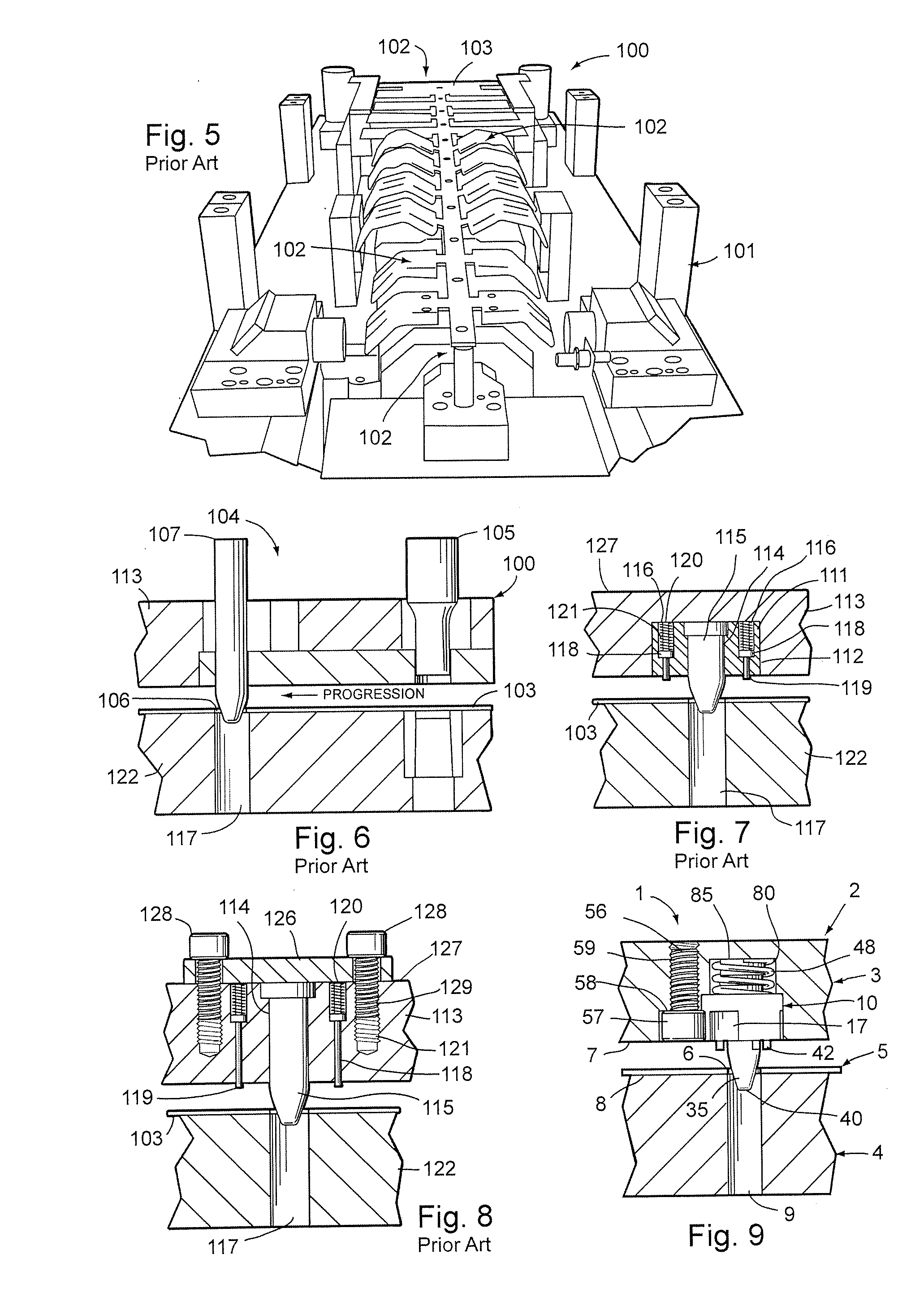
Current die making processes require carefully machined, precision holes and recesses in the die set for mounting the individual components, such that the same are quite labor intensive, and require substantial lead time to make, test and set up in a stamping press.
Consequently, such metal forming dies are very expensive to design, manufacture

Method used


Image

  • Modular pilot assembly with self-contained stripper and method for metal forming dies
  • Modular pilot assembly with self-contained stripper and method for metal forming dies
  • Modular pilot assembly with self-contained stripper and method for metal forming dies

Examples


Example

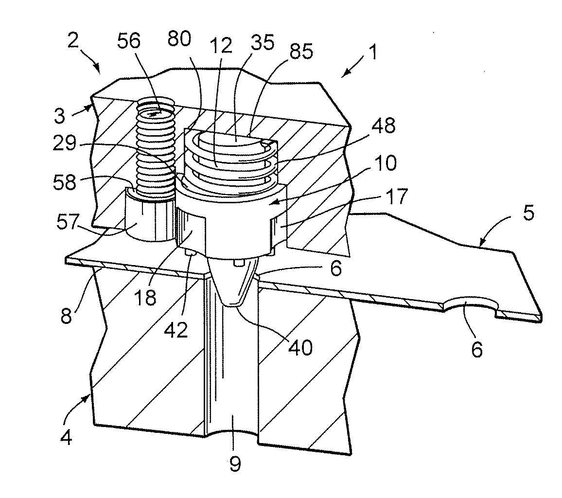
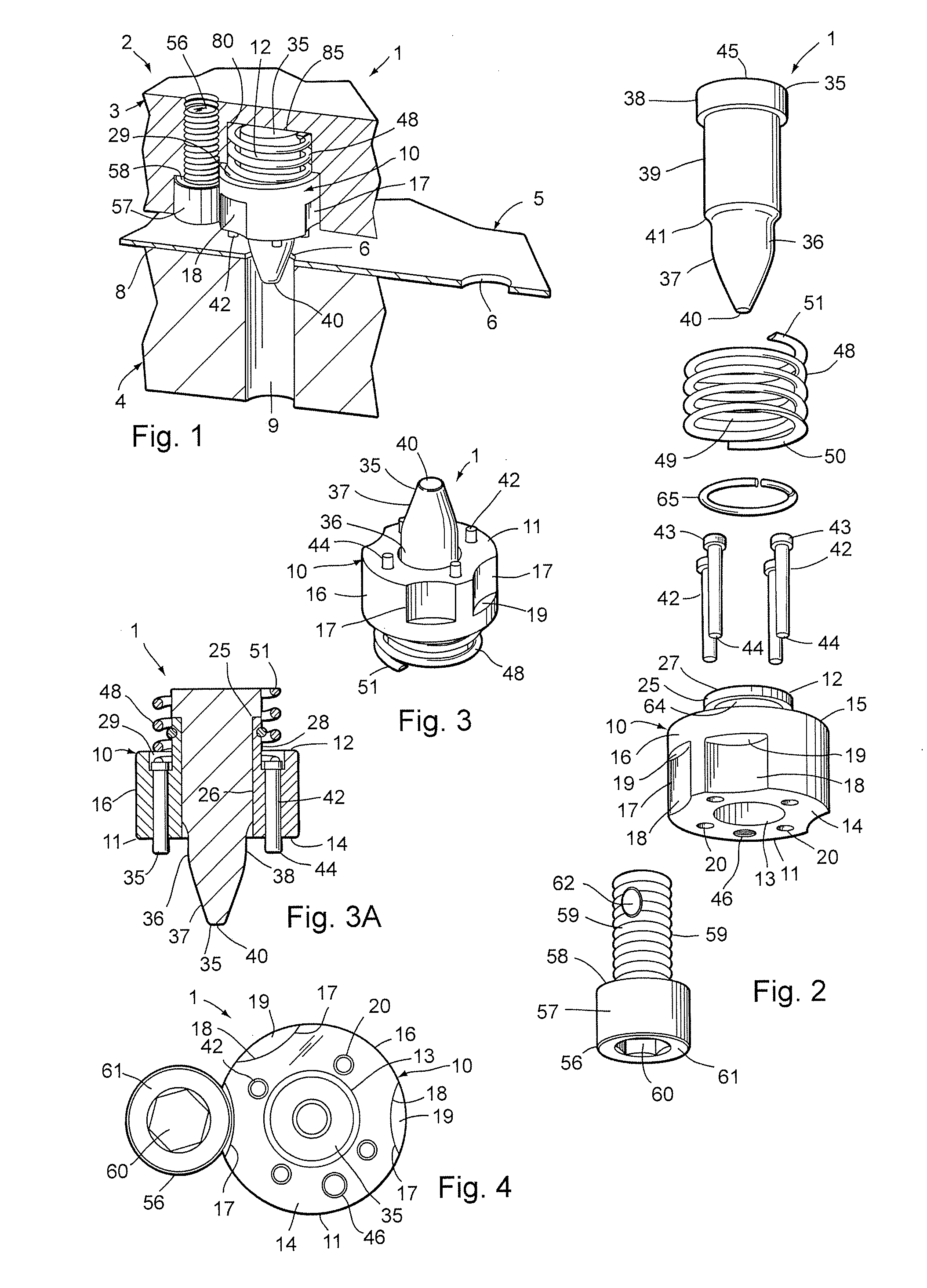
[0058]For purposes of description herein, the terms “upper,”“lower,”“right,”“left,”“rear,”“front,”“vertical,”“horizontal” and derivatives thereof shall relate to the invention as oriented in FIGS. 1, 2 and 3A. However, it is to be understood that the invention may assume various alternative orientations and step sequences, except where expressly specified to the contrary. It is also to be understood that the specific devices and processes illustrated in the attached drawings, and described in the following specification, are simply exemplary embodiments of the inventive concepts defined in the appended claims. Hence, specific dimensions and other physical characteristics relating to the embodiments disclosed herein are not to be considered as limiting, unless the claims expressly state otherwise.

[0059]The reference numeral 1 (FIGS. 1-4) generally designates a modular pilot assembly with self-contained stripper embodying the present invention. As shown in FIG. 1, the pilot assembly 1...


PUM

PropertyMeasurementUnit
Forceaaaaaaaaaa
Diameteraaaaaaaaaa
Sizeaaaaaaaaaa

Abstract

A pilot assembly and method has a cylindrical pilot sleeve with an apertured outer end in which a separate pilot pin is received, a grooved inner end, and a central portion with at least one inwardly curved sidewall relief, as well as internally mounted reciprocating ejector pins with outer ends that protrude through holes in the outer body end to strip stock from the pilot pin. A spring has its outer end mounted in the sleeve groove, and an inner end captured in a die pocket in a pretensed condition. A mounting screw has an enlarged head that has at least a portion thereof fit into the pilot sidewall relief, and a threaded shank that anchors the pilot sleeve in the die.

Description

CROSS REFERENCE TO RELATED APPLICATIONS AND CLAIM TO PRIORITY[0001]The present application is related to commonly assigned, co-pending U.S. provisional patent application Ser. No. 61 / 581,311, filed Dec. 29, 2011, entitled PILOT SLEEVE AND METHOD FOR METAL FORMING DIES AND THE LIKE, which is incorporated herein by reference, and claims priority thereto under 35 U.S.C. §119, as well as copending U.S. non-provisional patent application Ser. No. ______, filed even date herewith, entitled MODULAR PILOT ASSEMBLY WITH SELF-CONTAINED STRIPPER AND METHOD, which is also incorporated herein by reference.BACKGROUND OF THE INVENTION[0002]The present invention relates to metal forming dies and the like, and in particular to a modular pilot assembly with self-contained stripper and associated method.[0003]Metal forming dies, such as stamping dies and the like, are well known in the art. Progressive metal forming dies are unique, very sophisticated mechanisms which have multiple stations or progres...

Claims


Application Information

Patent Timeline
IPC IPC(8): B21J13/14B23P15/24B21J13/02
CPCB21K27/04B21D43/06B21D37/08
Inventor BREEN, SCOTT M.PYPER, JOEL T.
Owner STANDARD LIFTERS INC
Why Eureka
Try Eureka