Perforators

a perforator and perforation technology, applied in the field of perforators, can solve the problems of substantially harmless debris from the initiation of such a perforator, and the use of non-uniform distribution of filler, and achieve the effect of mitigating the effects of debris

Active Publication Date: 2012-12-04
QINETIQ LTD
View PDF10 Cites 6 Cited by
  • Summary
  • Abstract
  • Description
  • Claims
  • Application Information

AI Technical Summary

Benefits of technology

[0009]Preferably, the non-explosive filler is distributed homogeneously throughout the matrix. However, a non-uniform distribution of filler may be employed where this brings about a particular effect in terms of size of hole and / or depth of penetration. Such tuning of the characteristics is achieved relatively straightforwardly through controlling the introduction of the filler during manufacture of the liner. In use, it may be found effective to tune a liner so at to suit a particular formation and the nature of the desired perforation. By utilising a plastics material matrix as a case, hitherto inaccessible volumes of rapid and large scale production may be opened up. Advantageously, the plastics material matrix may be selected to have frangible if not friable characteristics. Consequently, debris from the initiation of such a perforator may be rendered substantially harmless or at least less damaging than conventionally formed cases to structures surrounding the perforator. In addition, the debris will itself be inert inasmuch as it should not facilitate or otherwise cause corrosion in other downhole components of the completion.
[0023]According to a further aspect of the invention there is provided a method of improving fluid outflow from a well borehole the method comprising perforating the borehole by means of a perforating gun according to the present invention.
[0024]Advantageously, subsequent recovery of fluids (e.g. hydrocarbons (oil or gas), water, or steam) from the well may be enhanced since use of liners and / or cases according to the present invention may provide improved penetration into the surrounding rock strata and / or mitigate the effects of debris left in the well shaft after penetration.

Problems solved by technology

However, a non-uniform distribution of filler may be employed where this brings about a particular effect in terms of size of hole and / or depth of penetration.
Consequently, debris from the initiation of such a perforator may be rendered substantially harmless or at least less damaging than conventionally formed cases to structures surrounding the perforator.
In addition, the debris will itself be inert inasmuch as it should not facilitate or otherwise cause corrosion in other downhole components of the completion.

Method used


Image

  • Perforators
  • Perforators
  • Perforators

Examples


Embodiment Construction

[0036]In the following, any references to the term gun are intended to encompass the term carrier and vice versa.

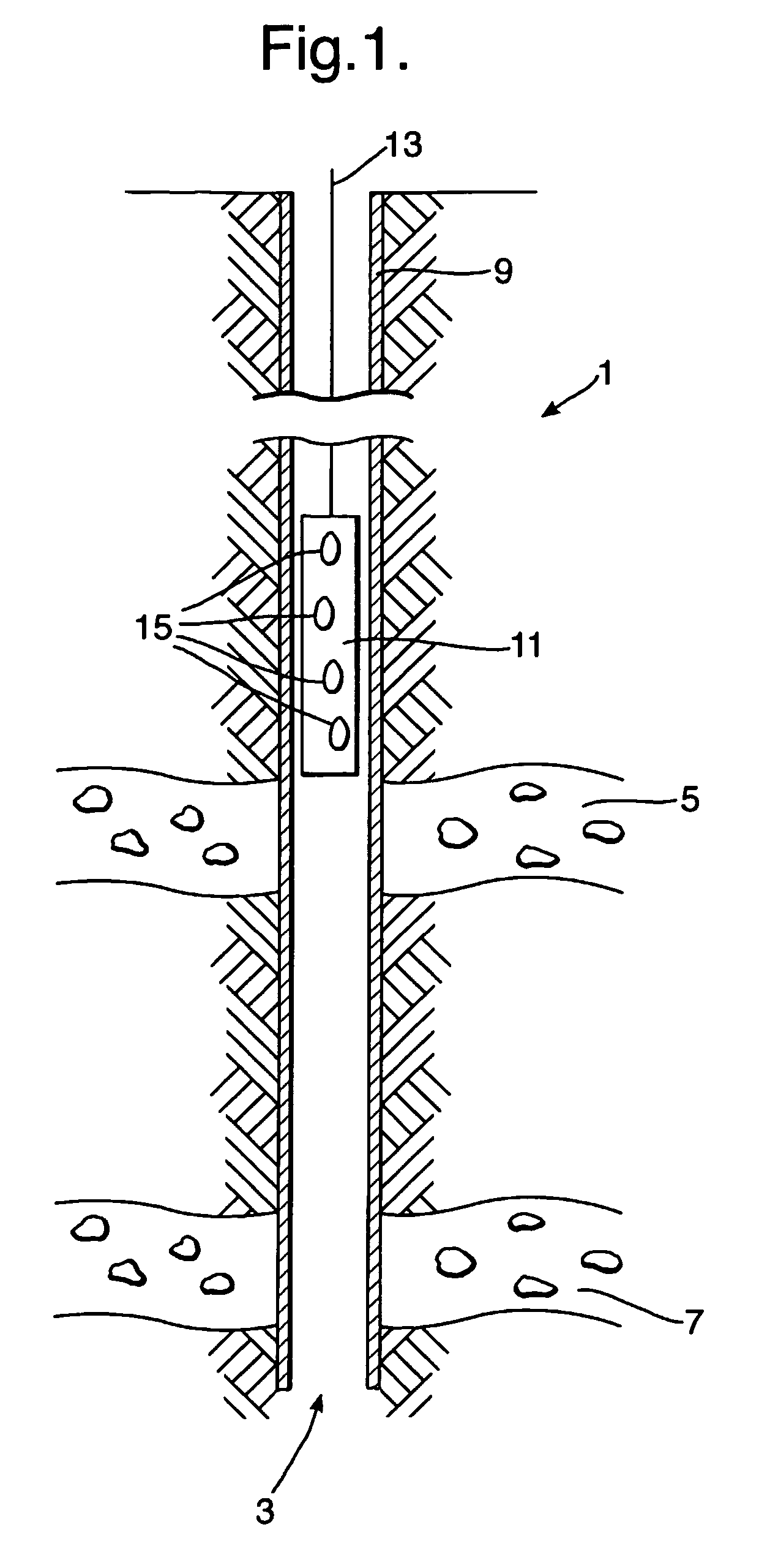
[0037]With reference to FIG. 1, there is shown a stage in the completion of a well 1 in which, the well bore 3 has been drilled into a pair of producing zones 5,7 in, respectively, unconsolidated and consolidated formations. A steel tubular or casing 9 is cemented within the bore 3 and in order to provide a flow path from the production zones 5,7 into the eventual annulus that will be formed between the casing 9 and production tubing (not shown) which will be present within the completed well, it is necessary to perforate the casing 9. In order to form perforations in the casing 9, a gun 11 is lowered into the casing on a wireline, slickline or coiled tubing 13, as appropriate.

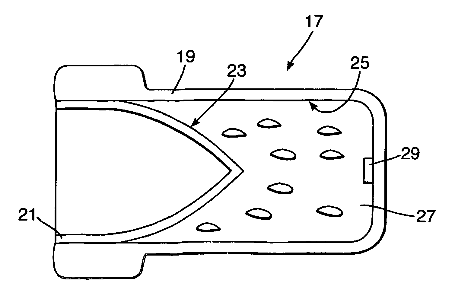
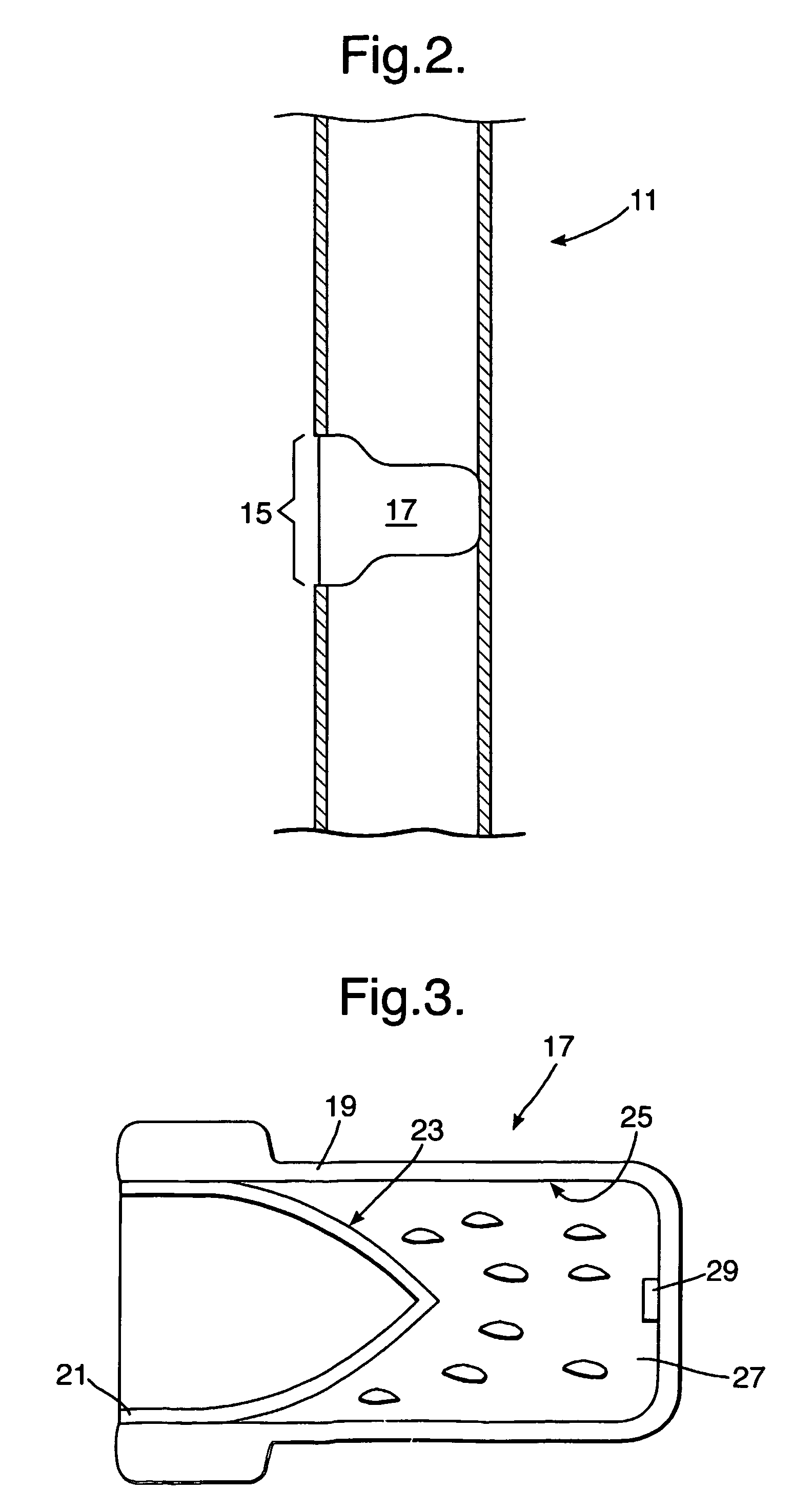
[0038]As is shown in more detail in FIG. 2, the gun 11 is a generally hollow tube of steel in this are formed ports 15 through which perforator charges 17 are fired. The diameter of the gun 11 is se...


PUM


Abstract

A composite material case (19) and liner (21) is described for use in a perforator (17) for completing wells such as oil, gas and water wells (1). The materials selected are intended to exhibit stability during prolonged periods at the raised temperatures and pressures present in a well (1).

Description

FIELD OF THE INVENTION[0001]The present invention relates to a perforator for use in perforating and fracturing well completions particularly, although not exclusively, perforators for use in tubing conveyed perforating guns for explosively perforating a well-bore casing, or perforating guns lowered on a slick line for perforating a tubing string or drill pipe string of wells such as, for example, oil, gas, water and steam wells.BACKGROUND TO THE INVENTION[0002]By far the most significant process in carrying out a completion in a cased well is that of providing a flow path between the production zone, also known as a formation, and the well bore. Typically, the creation of such a flow path is carried out using a perforator, with the resulting aperture in the casing and physical penetration into the formation via a cementing layer being commonly referred to as a perforation. Although mechanical perforating devices are known, almost overwhelmingly such perforations are formed using en...

Claims


Application Information

Patent Timeline
Patent Type & Authority Patents(United States)
IPC IPC(8): F42B1/02F42B1/032F42B3/28
CPCF42B3/28F42B1/032
Inventor MEDDES, RUSSELL VAUGHANHINTON, MICHAEL JOHN
Owner QINETIQ LTD
Why Eureka
Try Eureka