Label of radio frequency identification by thermal transfer printing antenna

a radio frequency identification and thermal transfer printing technology, applied in the direction of resonant antennas, burglar alarm mechanical actuation, instruments, etc., can solve the problems of inability to be used repeatedly and updated, easy to be damaged by foreign forces, and high cost, so as to achieve quick mass production and reduce cost

Inactive Publication Date: 2007-05-03
YANG SAN LIEN
View PDF2 Cites 14 Cited by
  • Summary
  • Abstract
  • Description
  • Claims
  • Application Information

AI Technical Summary

Benefits of technology

[0009] The main characteristics of the invention are mainly a thermal transfer printing antenna RFID substratum and a RFID chip. A conductive metal foil is used as a material to transfer the antenna onto a substratum by thermal transfer printing to form the antenna substratum, which is then adhered with the RFID chip by a flip chip bonder or a wire bonder. Then, a protective resin is coated on the chip, forming a single-layer thermal transfer printing antenna RFID label. The single-layer thermal transfer printing antenna RFID label can be further adhered with an upper protective layer to form a multi-layer thermal transfer printing antenna RFID label. The process can result in a quick mass production and a lower cost.

Problems solved by technology

Although the Barcode label attached on an object is easy to produce, low in cost and not affected by metal or conductive environment or electromagnetic wave, it is easy to be damaged by a foreign force, disabling it to be identified, and can't be used repeatedly and updated.
As for the current RFID label, although it is not easy to be damaged and capable to be used repeatedly and updated, but, due to a conductive metal antenna having to be produced by etching or carving, it costs high and needs a long time for manufacturing.
The identity component is a Barcode attached on a goods, and it is easily to be damaged or fall off, becoming impossible to be identified, and it can not be used repeatedly or updated
The identity compoments is a current RFID label, which costs high and need rather a long time to make.

Method used


Image

  • Label of radio frequency identification by thermal transfer printing antenna
  • Label of radio frequency identification by thermal transfer printing antenna
  • Label of radio frequency identification by thermal transfer printing antenna

Examples


Embodiment Construction

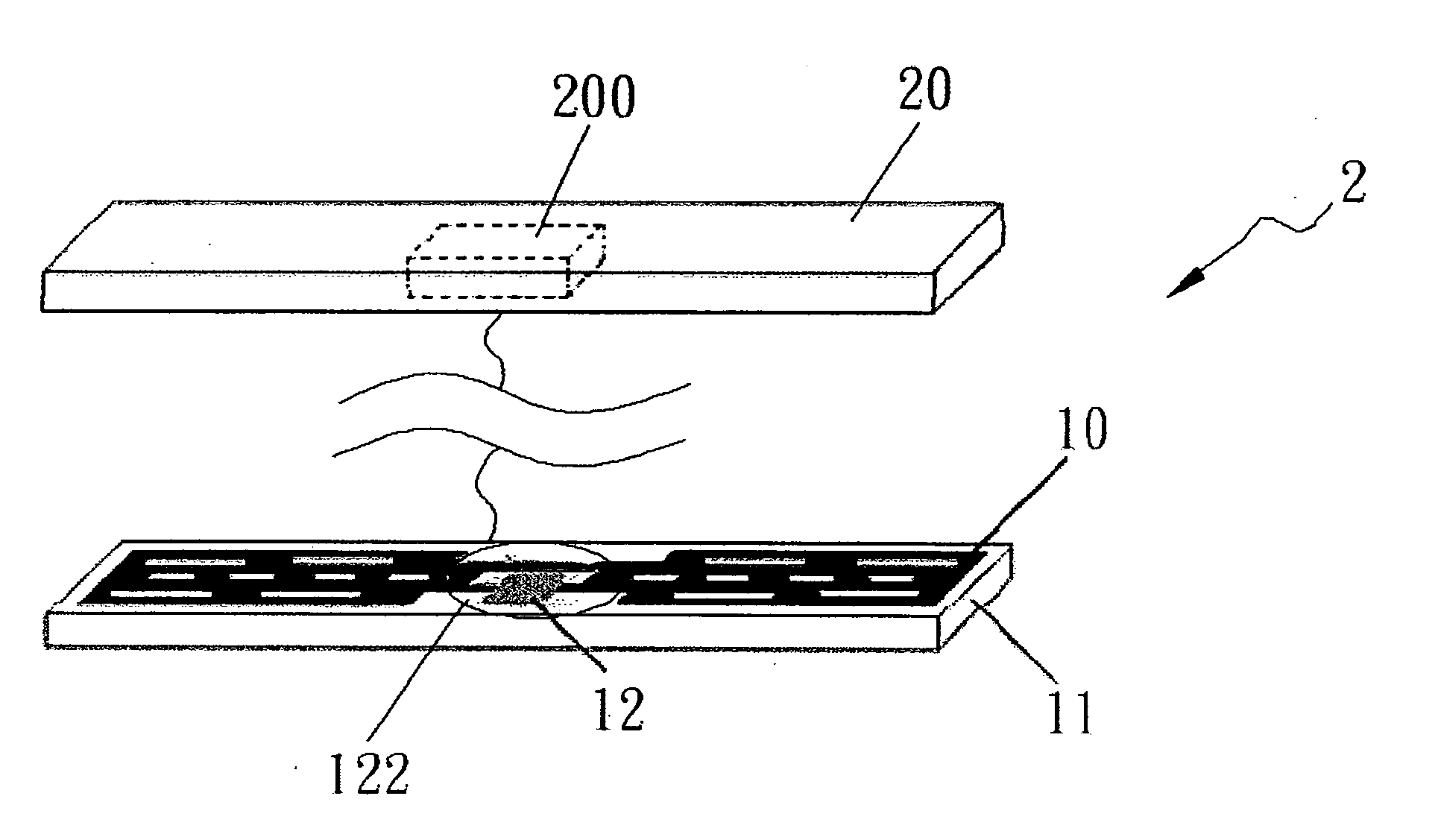
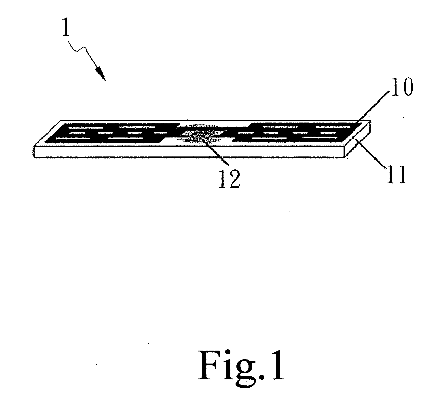
[0017] As shown in FIG. 1, a preferred embodiment of a thermal transfer printing antenna RFID label by a thermal transfer printing 1 in the present invention includes mainly an antenna 10, a RFID antenna substratum 11 and a RFID chip 12. Their related technologies are described as below.

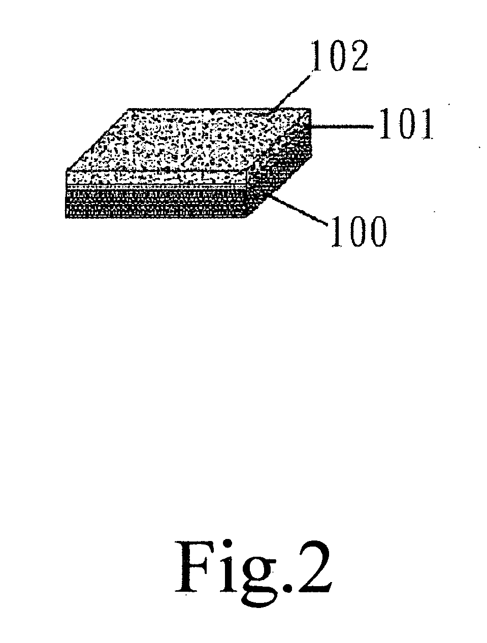
[0018] As shown in FIGS. 2 and 3, for making a thermal transfer printable conductive metal foil 15, a carrier 100 is first coated with a isolated layer 101 and then, plating the metallic solution on the isolated layer 101 by means of vacuum plating, thus forming a conductive metal foil 103, which is successively coated with a glue 104 to make a thermal transfer printing conductive metal foil 105 The carrier 100 is used as a substrate for vacuum plating. The isolated layer 101 is located between the carrier 100 and the metal foil 102, enabling the metal foil 102 to be peeled off the carrier 100 easily. Thus, the metal foil 103 is constituted as shown in FIG. 2. The glue layer 104 is an adhesive to co...


PUM

PropertyMeasurementUnit
conductiveaaaaaaaaaa
shapeaaaaaaaaaa
massaaaaaaaaaa

Abstract

A thermal transfer printing antenna RFID label by a thermal transfer printer includes mainly a conductive metal foil, a thermal transfer RFID antenna substratum and a RFID chip. A conductive metal foil is used as a material to thermal transfer the antenna circuits onto the substratum by a thermal transfer printer, forming the antenna substratum, which is then adhered with the RFID chip by a flip chip bonder or a wire bonder. The process can obtain a quick mass production and a lower cost for the label.

Description

BACKGROUND OF THE INVENTION [0001] 1. Field of the invention [0002] This invention relates to a label of radio frequency identification (hereafter:RFID) by a thermal transfer printing antenna, particularly to one using a conductive metal foil as a material to print an antenna on a substratum by a thermal transfer printer to form an antenna substratum, which is then adhered with a RFID chip by a flip chip bonder or a wire bonder, obtaining a quick mass production and a lower cost of the RFID label. [0003] 2. Description of the Prior Art [0004] Commonly, in order to speed up passing of an object through a checkpoint or a cashier, an identity component is always applied. Most of the identity data used conventionally are based on a Barcode label or a current RFID label. Although the Barcode label attached on an object is easy to produce, low in cost and not affected by metal or conductive environment or electromagnetic wave, it is easy to be damaged by a foreign force, disabling it to b...

Claims


Application Information

Patent Timeline
Patent Type & Authority Applications(United States)
IPC IPC(8): G08B13/14H01Q17/00
CPCH01Q1/2225Y10T29/49018H01Q9/285H01Q9/24
Inventor YANG, SAN-LIEN
Owner YANG SAN LIEN
Why Eureka
Try Eureka