Lead frame assembly, lead frame and insulating housing combination, and led module having the same

a technology of led modules and lead frame assemblies, which is applied in the direction of semiconductor devices, semiconductor/solid-state device details, electrical apparatus, etc., can solve the problems of difficulty in aligning the light emitting dies with the printed circuit board during the soldering process, and achieve the effect of fast mass production

Active Publication Date: 2010-03-25
LITE ON ELECTRONICS (GUANGZHOU) LTD +1
View PDF2 Cites 14 Cited by
  • Summary
  • Abstract
  • Description
  • Claims
  • Application Information

AI Technical Summary

Benefits of technology

[0007]According to an aspect of this invention, there is provided a light emitting diode (LED) module having a plurality of lead frame sets. Each of the conductive lead frame set comprises a first lead frame unit having a pair of first and second frame portions extending along a first direction and spaced apart from each other along a second direction different from the first direction, and at least two second lead frame units disposed between the first and second frame portions and spaced apart from each other along the second direction. Each of the second lead frame units cooperates with the first lead frame unit to define at least one first die-bonding area therebetween. An insulating housing is molded on the lead frame set and has a plurality of cavities. Each of the first die-bonding areas of the conductive lead frame set is exposed within a corresponding one of the cavities. A plurality of light emitting dies are mounted respectively at the first die-bonding areas of the conductive lead frame set. Due to inclusion of the conductive lead frame set in the LED module, a printed circuit board can be omitted to thereby facilitate fast mass production.

Problems solved by technology

However, since the size of the light emitting dies is small, it is difficult to align the light emitting dies with the printed circuit board during the soldering processes.

Method used


Image

  • Lead frame assembly, lead frame and insulating housing combination, and led module having the same
  • Lead frame assembly, lead frame and insulating housing combination, and led module having the same
  • Lead frame assembly, lead frame and insulating housing combination, and led module having the same

Examples


first embodiment

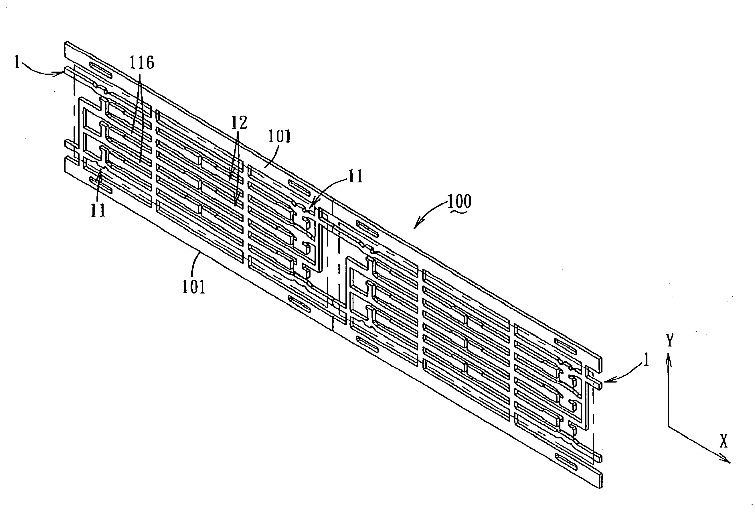
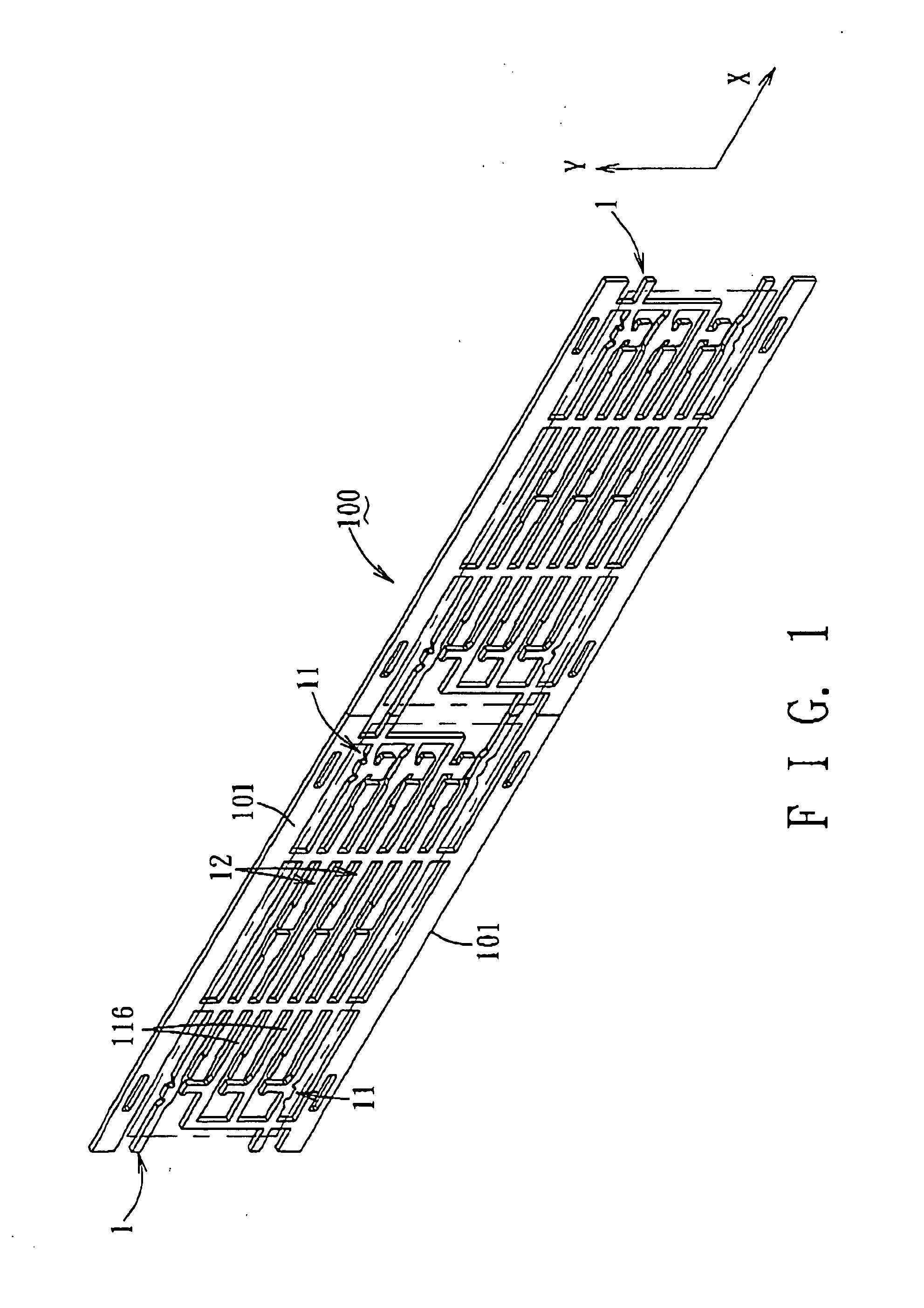
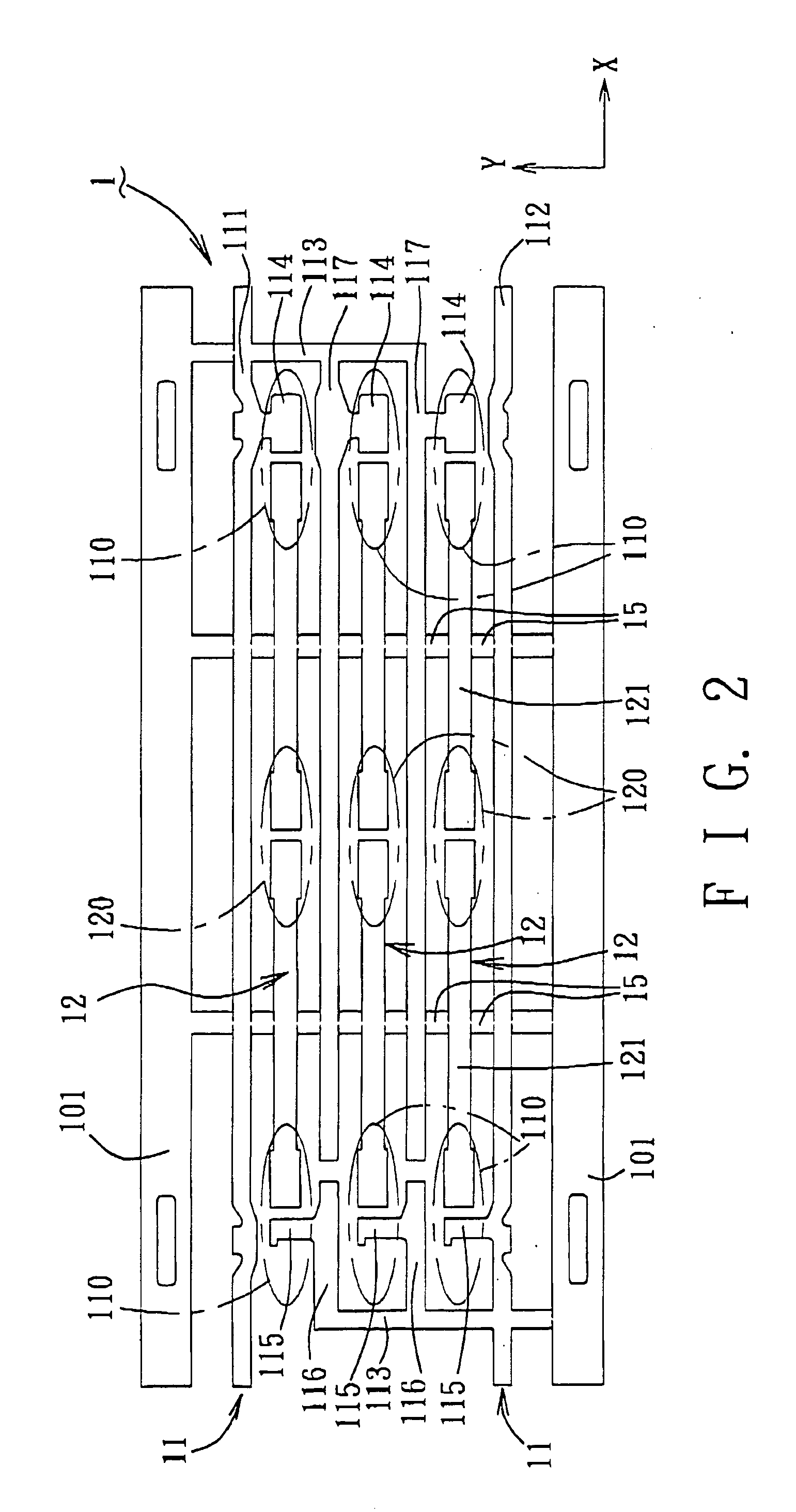
[0030]As shown in FIG. 9, a modified unitary conductive lead frame assembly 100 of a second preferred embodiment of this invention has a structure similar to that of the first embodiment, and comprises a plurality of lead frame sets 1 (only one is shown). The main difference between the lead frame assembly 100 of the second preferred embodiment and the first preferred embodiment resides in the configuration of the first lead frame unit and the second lead frame units 12. In the second preferred embodiment, the first lead frames 11 respectively have a first protuberance 114 and a second protuberance 115 each extending from a respective one of the first and second frame portions 111, 112 along the second direction (Y). Each of the second lead frame units 12 comprises a third frame portion 121 disposed between the first and second protuberances 114, 115 of the first lead frames 11. The third frame portion 121 has two ends each cooperating with a corresponding one of the protuberances 1...

third embodiment

[0032]As shown in FIG. 11, a modified unitary conductive lead frame assembly 100 of a fourth preferred embodiment of this invention has a structure similar to that of the The main difference between the lead frame assemblies 100 of the fourth preferred embodiment and the third preferred embodiment resides in the configuration of the first lead frame unit. In the fourth preferred embodiment, the first lead frames 11 further include respectively branch frame portions 118, 119 each extending from a respective one of the first and second frame portions 111, 112 along the second direction (Y) toward the other one of the first and second frame portions 111, 112, such that an antistatic member 2 may be disposed therebetween. After the insulating housings 3 (see FIG. 4) are molded respectively on the lead frame sets 1, the connecting strips 15 can be removed. The fourth preferred embodiment has the same advantages as those of the first preferred embodiment.


PUM


Abstract

A unitary lead frame assembly having a plurality of lead frame sets each comprises a first lead frame unit. The first lead frame unit has a pair of first and second frame portions extending along a first direction and spaced apart from each other along a second direction different from the first direction. The lead frame set further comprises at least two second lead frame units disposed between the first and second frame portions and spaced apart from each other along the second direction. Each of the second lead frame units cooperates with the first lead frame unit to define at least one first die-bonding area therebetween.

Description

CROSS-REFERENCE TO RELATED APPLICATIONS[0001]This application claims priority of Chinese Application No. 200810198897.8, filed on Sep. 25, 2008, and Chinese Application No. 200910037696.4, filed on Mar. 5, 2009.BACKGROUND OF THE INVENTION[0002]1. Field of the Invention[0003]The invention relates to a light emitting diode (LED) module, more particularly to an LED module comprising a unitary conductive lead frame assembly adapted for mounting light emitting dies.[0004]2. Description of the Related Art[0005]A conventional panel light source employs a plurality of light emitting dies as light sources. The light emitting dies are disposed on a printed circuit board through reflow soldering and wave soldering processes. However, since the size of the light emitting dies is small, it is difficult to align the light emitting dies with the printed circuit board during the soldering processes.SUMMARY OF THE INVENTION[0006]Therefore, the object of the present invention is to provide an improve...

Claims


Application Information

Patent Timeline
Patent Type & Authority Applications(United States)
IPC IPC(8): H01L33/00H01L23/495
CPCH01L23/49537H01L33/483H01L33/62H01L24/48H01L2224/48091H01L2924/00014H01L2924/12041H01L2924/00H01L2224/45099H01L2224/45015H01L2924/207
Inventor HUANG, SHIH-CHUNGLIN, CHEN-HSIUCHOU, MENG-SUNG
Owner LITE ON ELECTRONICS (GUANGZHOU) LTD
Why Eureka
Try Eureka