Single roller slide-out mechanism

a single roller, slide-out technology, applied in the direction of transportation and packaging, transportation items, transportation vehicles, etc., can solve the problems of inconvenient or unsightly design, heavy and bulky underlying structure used in such slide-outs, increasing production costs and weight, and achieves the effect of less expensive manufacturing

Active Publication Date: 2009-06-02
DEXTER AXLE CO LLC
View PDF66 Cites 24 Cited by
  • Summary
  • Abstract
  • Description
  • Claims
  • Application Information

AI Technical Summary

Benefits of technology

[0009]It is another object of the present invention to provide a slide-out system that is less expensive to manufacture than prior art designs.
[0010]It is another object of the present invention to provide a slide-out system that is lighter than prior art designs.
[0011]In one embodiment, the present invention attempts to achieve these objects with a slide-out system comprising an inner rail that slides into and out of an inner rail. The inner rail is supported within the outer rail by a single support roller and a retaining slide, while a rail gear drives a gear rack on the inner rail to cause extension or retraction. The support roller is asymmetrically positioned under a width of the inner rail (e.q., on one side of the width of the rail). Similarly, the rail gear and gear rack are asymmetrically positioned under the width of the inner rail, opposite the support roller. Additional support is provided by a retaining slide attached to the inner rail that slides against retaining lip on the outer rail. In this respect, the single support roller, the retaining slide and, in some cases, the rail gear provide at least some support to the inner rail. This arrangement allows the rails of the slide-out system to be narrower than those used in many popular flush-floor slide-out systems in use today.

Problems solved by technology

As a result, there is typically adequate space within the vehicle's interior to accommodate users in transit and remain within the standard width limitations imposed upon a vehicle.
To some users, this type of design was inconvenient or unsightly.
Regardless of which type of slide-out rooms are used today, the underlying structure that is used in such slide-outs is typically heavy and bulky.
While providing adequate support for a slide-out room, these sliding members require more material to manufacture, increasing both their production cost and weight.

Method used


Image

  • Single roller slide-out mechanism
  • Single roller slide-out mechanism
  • Single roller slide-out mechanism

Examples


Embodiment Construction

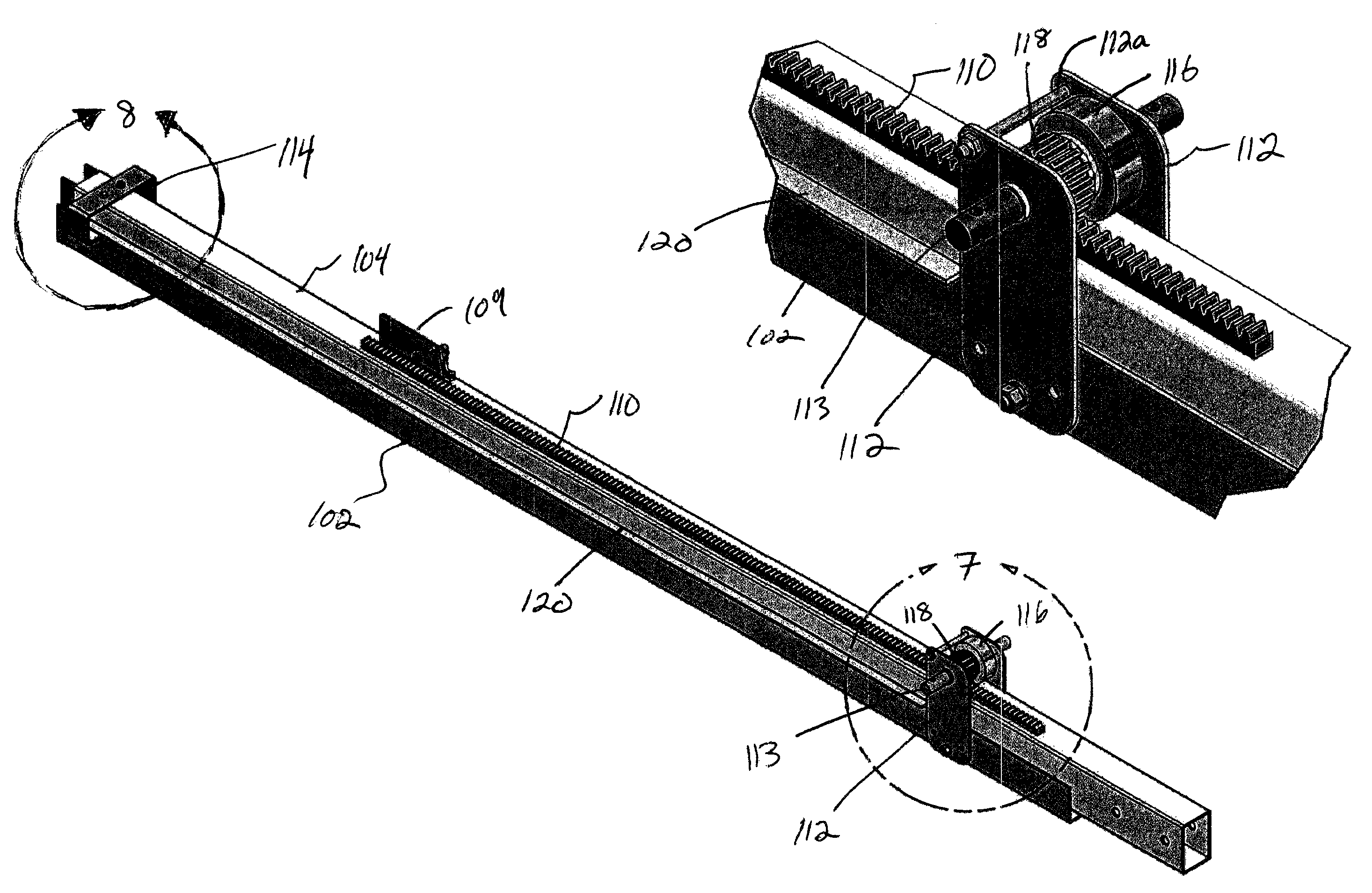
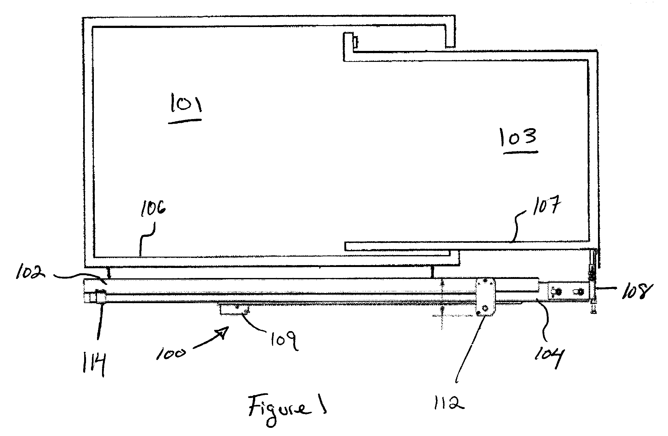
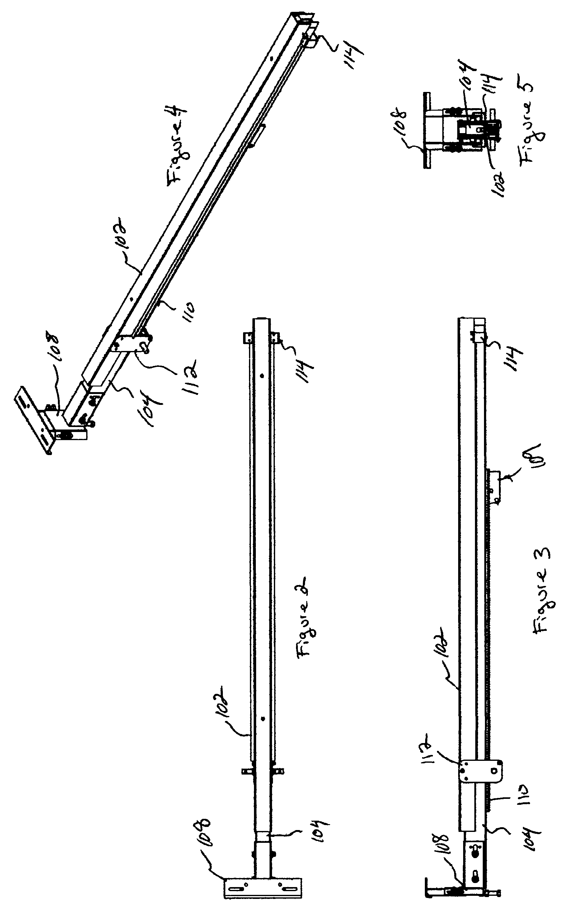
[0031]FIGS. 1-9 illustrate a preferred embodiment of a slide-out system 100 according to the present invention which includes an outer rail 102 fixed to a vehicle 101 and an inner rail 104 coupled to a slide-out room 103. The outer rail 102 and the inner rail 104 are arranged in such a way, as described in detail below, as to reduce the complexity of the slide-out system 100, allowing for cost effective robotic welding. Further, the simplified design utilizes less raw material (typically steel) allowing for reductions in manufacturing costs and reductions in the final weight of the slide-out system 100.

[0032]Turning first to FIG. 1, a cross sectional view of the vehicle 102 is shown, including the slide-out room 103 which moves into and out of the slide-out room. Generally, the outer rail 102 is fixed below a main floor 106 of the vehicle 101 while the inner rail 104 is coupled to the bottom side of the floor 107 of the slide-out room 103 by a mounting bracket 108. The inner rail 10...


PUM


Abstract

In one embodiment, the present invention provides a slide-out system comprising an inner rail that slides into and out of an inner rail. The inner rail is supported within the outer rail by a single support roller and a retaining slide, while a rail gear drives a gear rack on the inner rail to cause extension or retraction. This arrangement allows the rails of the slide-out system to be narrower than those used in many popular flush-floor slide-out systems in use today.

Description

RELATED APPLICATIONS[0001]This application claims priority to U.S. Provisional Application Ser. No. 60 / 763,330 filed Jan. 30, 2006 entitled Single Roller Slide-Out Mechanism and is hereby incorporated by reference.BACKGROUND OF THE INVENTION[0002]In order to increase the available interior space of a motorized or towable vehicle such as a motor home, trailer, or boat, these vehicles have been designed to include slide-out rooms. When the vehicle is in transit, the slide-out room is retracted and stored in the vehicle's interior with the exterior wall of the slide-out room approximately flush with the vehicle's exterior. As a result, there is typically adequate space within the vehicle's interior to accommodate users in transit and remain within the standard width limitations imposed upon a vehicle. When the vehicle is parked and leveled, the slide-out room is then slid outward through an opening formed in a sidewall of the vehicle thereby increasing the internal accommodations.[0003...

Claims


Application Information

Patent Timeline
Patent Type & Authority Patents(United States)
IPC IPC(8): B60P3/34
CPCB60P3/34
Inventor REVELINO, LARRYPERVORSE, JOHN
Owner DEXTER AXLE CO LLC
Why Eureka
Try Eureka