Printed circuit board connector for utility meters

a technology of printed circuit board and utility meters, applied in the field of utility meters, can solve the problems of limiting the output mode of the basic mechanical form of the register, unable to generally encompass all of the desired characteristics, and unable to achieve the effect of generalization of all the desired characteristics, and achieves the effect of increasing stability

Inactive Publication Date: 2009-06-02
ITRON
View PDF15 Cites 34 Cited by
  • Summary
  • Abstract
  • Description
  • Claims
  • Application Information

AI Technical Summary

Benefits of technology

[0019]In one of its simpler forms, the present technology provides an unsecured printed circuit board edge card type connector that also assists in the providing physical support of the connected printed circuit boards.
[0023]In accordance with yet additional aspects of further embodiments of the present subject matter, apparatus and accompanying methodologies have been developed to provide a connector that, in concert with predetermined trace configurations on the individual printed circuit boards, may provide a “pass through” connection of signals and / or circuit board operating power from among a plurality of stacked printed circuit boards and / or may function to allow insertion of functional elements including various forms of signal processing between such a plurality of printed circuit boards by providing alternative signal paths for the various printed circuit boards in the multi-board stack.
[0024]According to yet still other aspects of additional embodiments of the present subject matter, apparatus and methodologies have been developed to insure that desired electrical functions are performed by the connector while at the same time the connector, by virtue of its physical connection to the multiple printed circuit boards, provides a measure of additional stability to the physical arrangement of the boards.

Problems solved by technology

The foregoing basic mechanical form of register was typically limited in its mode of output, so that only a very basic or lower level metrology function was achieved.
Implementing incremental changes in technology, such as retrofitting new features into existing equipment, or attempting to implement changes to basic components which make various components not interchangeable with other configurations already in the field, can generate considerable industry problems.
While various implementations of metrology devices have been developed, no design has emerged that generally encompasses all of the desired characteristics as hereafter presented in accordance with the subject technology.

Method used


Image

  • Printed circuit board connector for utility meters
  • Printed circuit board connector for utility meters
  • Printed circuit board connector for utility meters

Examples


Embodiment Construction

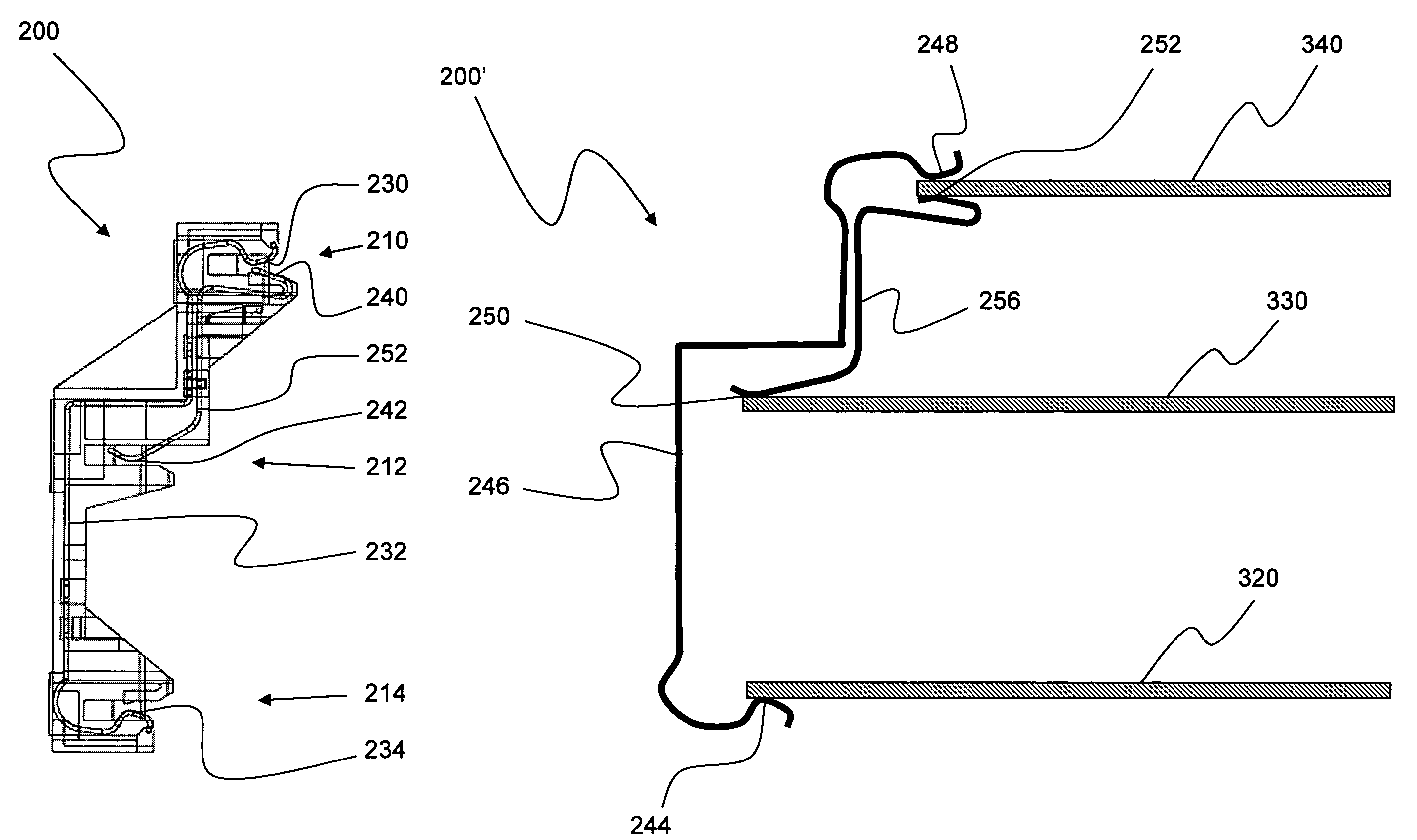
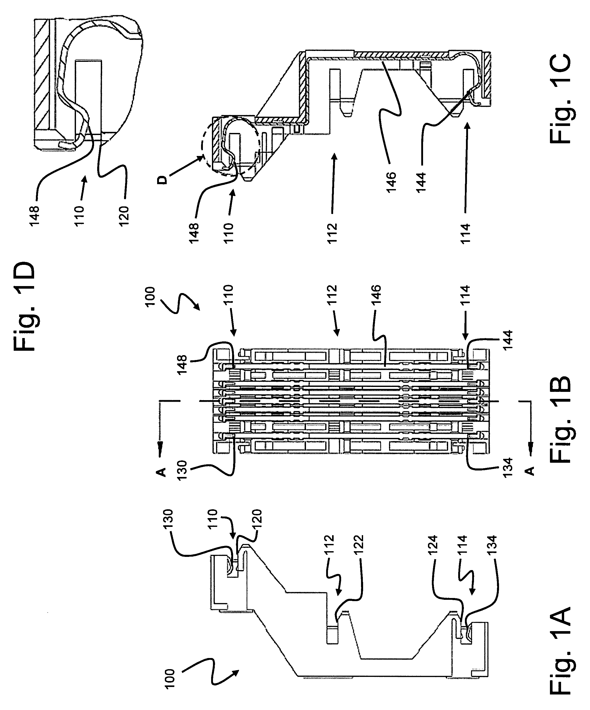
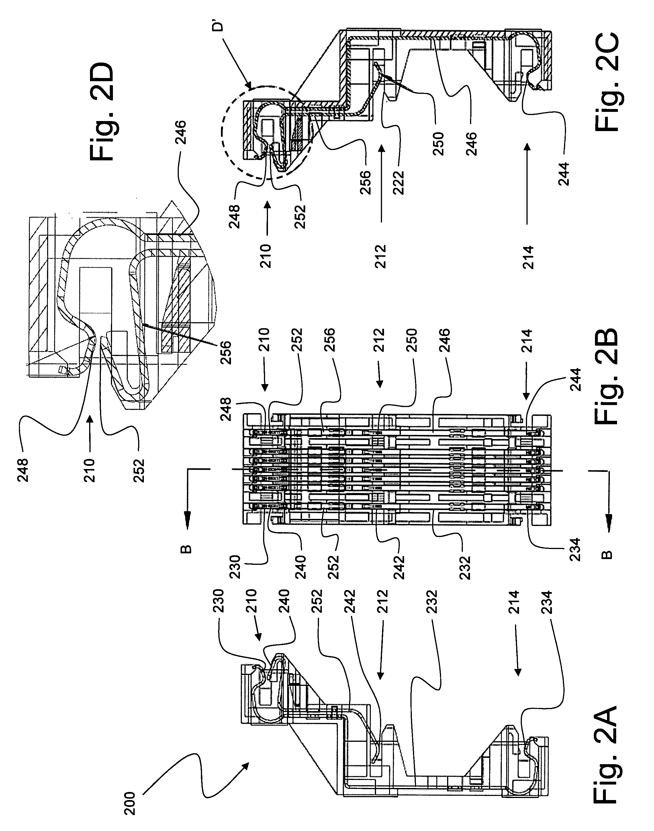
[0051]As discussed in the Summary of the Invention section, the present subject matter is particularly concerned with apparatus and methodology for electrically and physically coupling printed circuit boards together in a utility metrology environment.

[0052]Respectively selected combinations of aspects of the disclosed technology correspond to a plurality of respective different exemplary embodiments of the present subject matter. It should be noted that each of the exemplary embodiments presented and discussed herein should not insinuate limitations of the present subject matter. Features or steps illustrated or described as part of one embodiment may be used in combination with aspects of another embodiment to yield yet further embodiments. Additionally, certain features may be interchanged with similar devices or features not expressly mentioned which perform the same or similar function.

[0053]Moreover, it should be appreciated that, while the general discussion herein relates by...


PUM


Abstract

Disclosed are apparatus and methodology for coupling plural, spaced-apart printed circuit boards together within a utility meter. An individual, rigid connector is provided that, in concert with conductive edge traces on selected printed circuit boards, provides power and signal coupling alternatives for various printed circuit boards. The connector also provides added physical support for the printed circuit boards.

Description

PRIORITY CLAIM[0001]This application claims the benefit of previously filed U.S. Provisional Patent Application entitled “PRINTED CIRCUIT BOARD CONNECTOR FOR UTILITY METERS,” assigned U.S. Ser. No. 60 / 813,647, filed Jun. 14, 2006, and which is fully incorporated herein by reference for all purposes. Provisional Patent ApplicationFIELD OF THE INVENTION[0002]The present technology relates to utility meters. More particularly, the present technology relates to apparatus and methodologies for electrically and physically coupling a plurality of printed circuit boards together within a utility meter.BACKGROUND OF THE INVENTION[0003]The general object of metrology is to monitor one or more selected physical phenomena to permit a record of monitored events. Such basic purpose of metrology can be applied to a variety of metering devices used in a number of contexts. One broad area of measurement relates, for example, to utility meters. Such role may also specifically include, in such context...

Claims


Application Information

Patent Timeline
Patent Type & Authority Patents(United States)
IPC IPC(8): H01R33/945
CPCG01R22/065H01R9/096H01R29/00H05K7/1417H05K1/144H01R12/52
Inventor MAKINSON, DAVID N.PHILPOT, LUDLOW
Owner ITRON
Why Eureka
Try Eureka