Pollutant purification apparatus

a technology for purifying apparatus and polluted water, which is applied in the direction of water cleaning, sedimentation settling tank, centrifugal force sediment separation, etc., can solve the problems of water pollution, the treatment tank cannot discharge polluted water under, and the removal of a relatively small amount of polluted material from the treatment tank, so as to prevent floating materials

Inactive Publication Date: 2009-06-02
CHASEDAI ENVIRONMENT
View PDF12 Cites 10 Cited by
  • Summary
  • Abstract
  • Description
  • Claims
  • Application Information

AI Technical Summary

Benefits of technology

[0009]Therefore, the present invention has been made in view of the above problems, and it is an object of the present invention to provide an apparatus for purifying polluted water that can naturally remove polluted water that has become stagnant in a treatment tank.
[0012]Preferably, the apparatus further includes a baffle installed to the second outlet, for preventing floating materials floating on the polluted water from discharging while the polluted water is discharged through the second outlet.

Problems solved by technology

When such pollutants are washed into rivers along with rainwater, water pollution occurs.
That is, the treatment tank cannot discharge the polluted water under the point at which the outlet is installed.
Therefore, the polluted water under the outlet becomes stagnant in the treatment tank and then decays, causing odor.
Since the pump car pumps out stagnant polluted water as well as polluted materials, it can only remove a relatively small amount of polluted material from the treatment tank.
That is, the conventional pump car has a limitation in that it can only effectively pump the polluted materials once, which causes high maintenance fees to maintain the treatment tank.

Method used


Image

  • Pollutant purification apparatus
  • Pollutant purification apparatus
  • Pollutant purification apparatus

Examples


Embodiment Construction

[0040]The following description with reference to the accompanying drawings is provided to assist in a comprehensive understanding of exemplary embodiments of the invention as defined by the claims and their equivalents. It includes various specific details to assist in that understanding but these are to be regarded as merely exemplary. Accordingly, those of ordinary skill in the art will recognize that various changes and modifications of the embodiments described herein can be made without departing from the scope and spirit of the invention. Also, descriptions of well-known functions and constructions are omitted for clarity and conciseness.

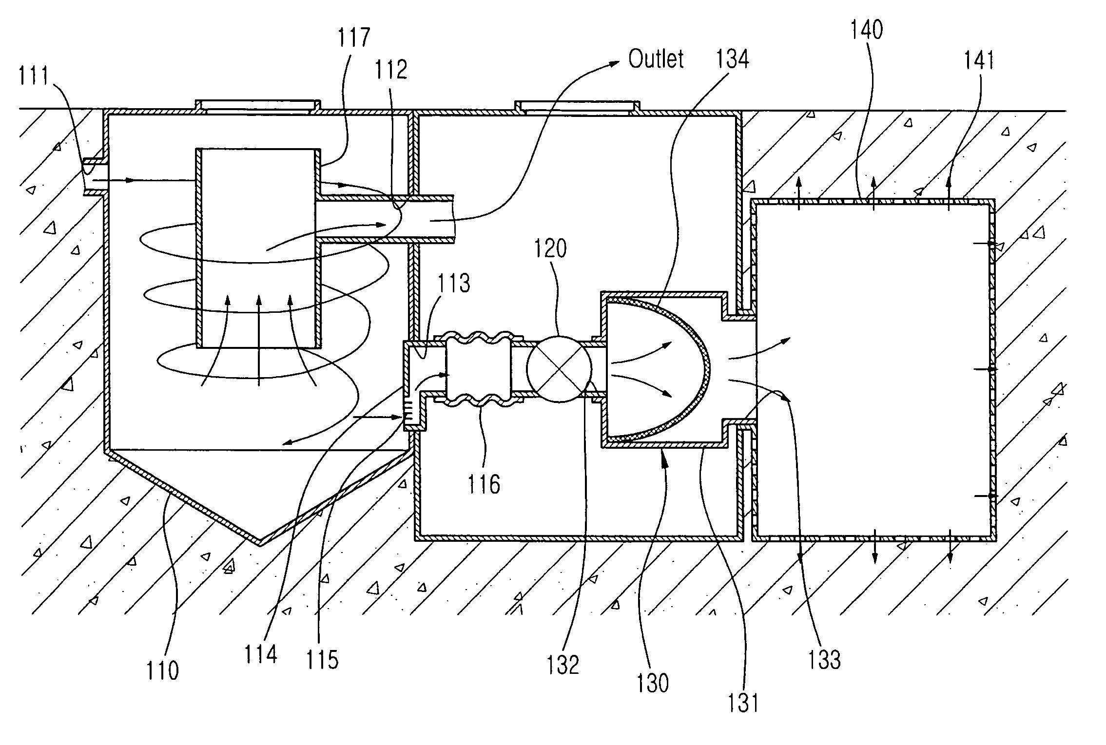
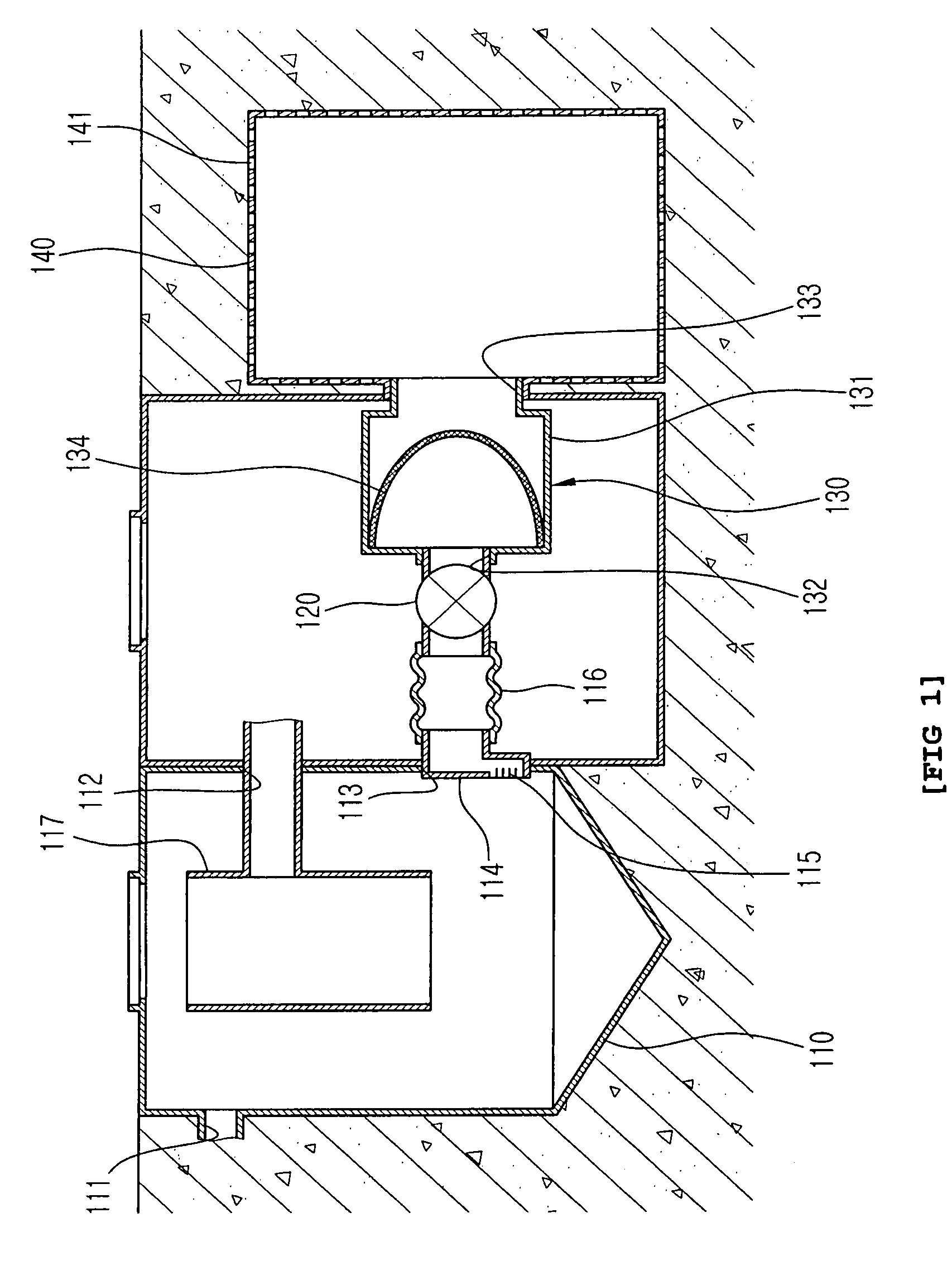
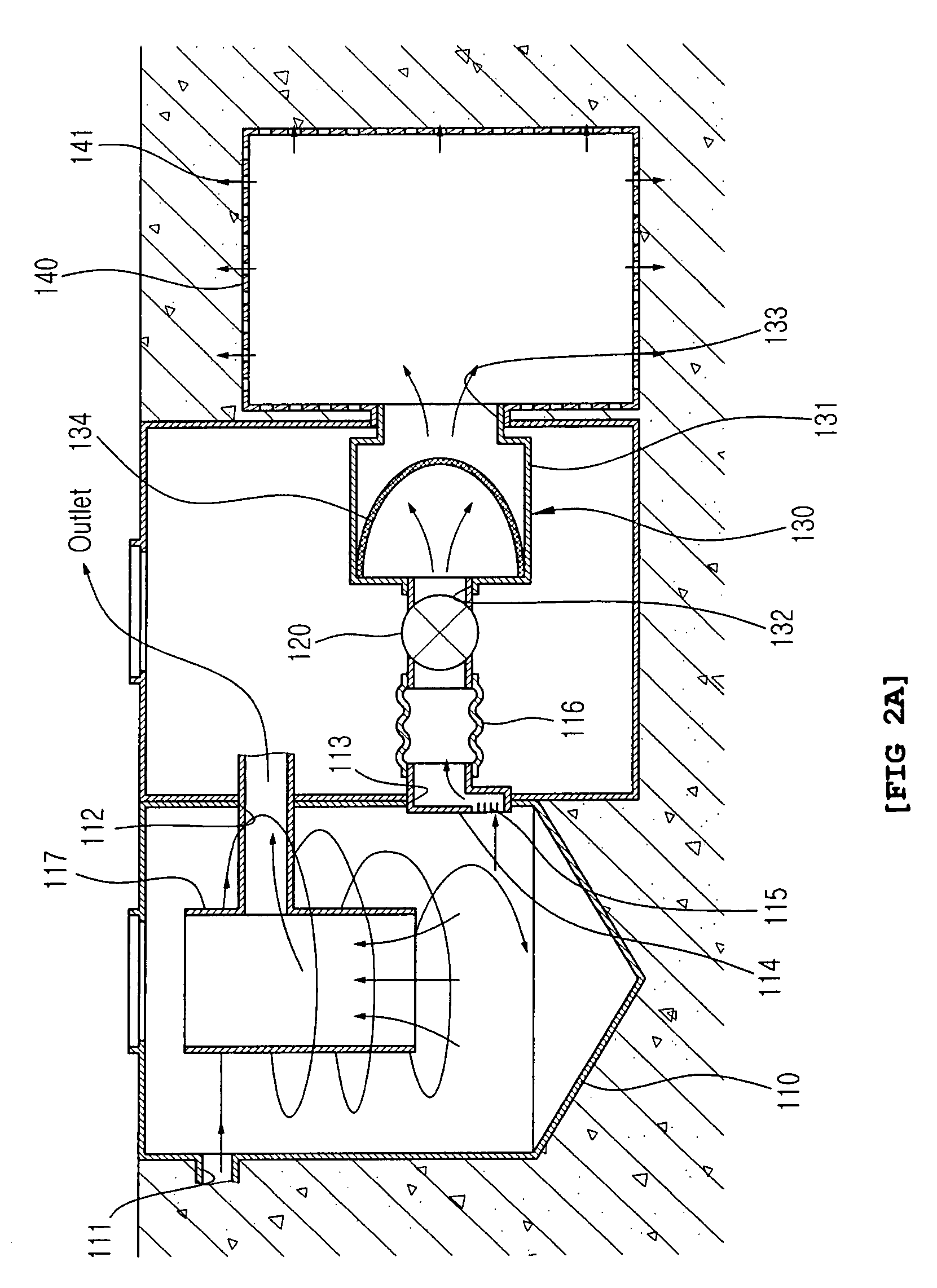
[0041]FIG. 1 is a cross-sectional view depicting an apparatus for purifying polluted water according to an exemplary embodiment of the present invention, which is configured to include a treatment tank 110, a valve 120, a pre-treatment device 130, and an infiltration tank 140.

[0042]The treatment tank 110 is implemented with a hydro-cyclone se...


PUM

PropertyMeasurementUnit
flexibleaaaaaaaaaa
physicalaaaaaaaaaa
chemical propertiesaaaaaaaaaa

Abstract

An apparatus for purifying polluted water is disclosed, which can naturally remove polluted water stagnated in a treatment tank. The apparatus includes a treatment tank and an infiltration tank. The treatment tank has an inlet at its one side, and first and second outlets at its other side. The treatment tank treats the polluted water that flows through the inlet and discharges the treated polluted water through the first outlet. The infiltration tank is connected to the second outlet and has a plurality of infiltration holes formed on the body thereof. The infiltration tank allows the treated polluted water that flows from the second outlet of the treatment tank to permeate into the ground though the plurality of infiltration holes. Since the polluted water stagnated in the treatment tank can be naturally released, odor due to decay of the polluted water and a subsequent insect infestation can be prevented. In addition, maintenance fees to maintain to the treatment tank can be reduced.

Description

PRIORITY[0001]This application claims the benefit under 35 U.S.C. § 119(a) of a Korean patent application filed on May 30, 2007 in the Korean Intellectual Property Office and assigned Serial No. 10-2007-0052786, and the entire disclosure of which is hereby incorporated by reference.BACKGROUND OF THE INVENTION[0002]1. Field of the Invention[0003]The present invention relates to technology of treatment of polluted water. More particularly, this invention relates to an apparatus for purifying polluted water that can remove polluted water that has not yet been discharged from a treatment tank.[0004]2. Description of the Related Art[0005]In general, polluted materials are classified into point source pollutants and non-point source pollutants according to their pollution source (point pollution source and non-point pollution source). The non-point pollution source refers to a source that generates pollutants without any particular discharging paths, such as dusts from vehicle exhaust and...

Claims


Application Information

Patent Timeline
Patent Type & Authority Patents(United States)
IPC IPC(8): E03F5/14
CPCB01D21/0012E03F11/00B01D21/26B01D21/267C02F1/38C02F2103/001B01D2221/12Y02A20/208C02F1/00
Inventor AN, YEONG-CHANJEONG, JAE-HONG
Owner CHASEDAI ENVIRONMENT
Why Eureka
Try Eureka