Parallel power supply with active droop current sharing circuit having current limiting function

a current limiting function and power supply technology, applied in the direction of electric variable regulation, process and machine control, instruments, etc., can solve the problems of imbalance in the sharing of load current among power converters, affecting the performance and reliability of parallel power supply systems, and relatively difficult to achieve exact current matching between parallel power supplies

Active Publication Date: 2009-06-02
DELTA ELECTRONICS (THAILAND) PUBLIC CO LTD +1
View PDF15 Cites 23 Cited by
  • Summary
  • Abstract
  • Description
  • Claims
  • Application Information

AI Technical Summary

Problems solved by technology

In many practical applications, however, parallel power supplies frequently experience variations in their respective output voltages due to factors such as temperature coefficient, aging and output impedance differences, thereby making exact current matching between parallel power supplies relatively difficult to achieve.
Though the current sharing technique can help a plurality of power converters share the load current equally, it is possible that an imbalance in the sharing of the load current among power converters would be generated when an abrupt change is occurred to the parallel power supply.
The unequal sharing of load current by the parallel power supplies may degrade the performance and reliability of a parallel power supply system.
This problem is of particular concern when the power converters use synchronous rectification due to the inherent feedback properties of these circuits.
The efficiency of the current-limited power converters is therefore relatively low, and the efficiency of the idling (sinking) power converters is effectively zero, since the sinking converter is delivering no power, but is consuming power.
Although the conventional parallel power supply of FIG. 1 is sufficient to provide current sharing among plural parallel power supplies and overcurrent protection capability, the prior art parallel power supply suffers several major disadvantages.
For example, the accuracy of current sharing in the conventional parallel power supply is limited.
Further, the conventional parallel power supply incorporates a large quantity of active elements in the active droop current sharing circuit and overcurrent detection scheme, which would result in a bulky electronic product.
Accordingly, the conventional parallel power supply will be oversized and lacks flexibility in circuit design.

Method used


Image

  • Parallel power supply with active droop current sharing circuit having current limiting function
  • Parallel power supply with active droop current sharing circuit having current limiting function
  • Parallel power supply with active droop current sharing circuit having current limiting function

Examples


Embodiment Construction

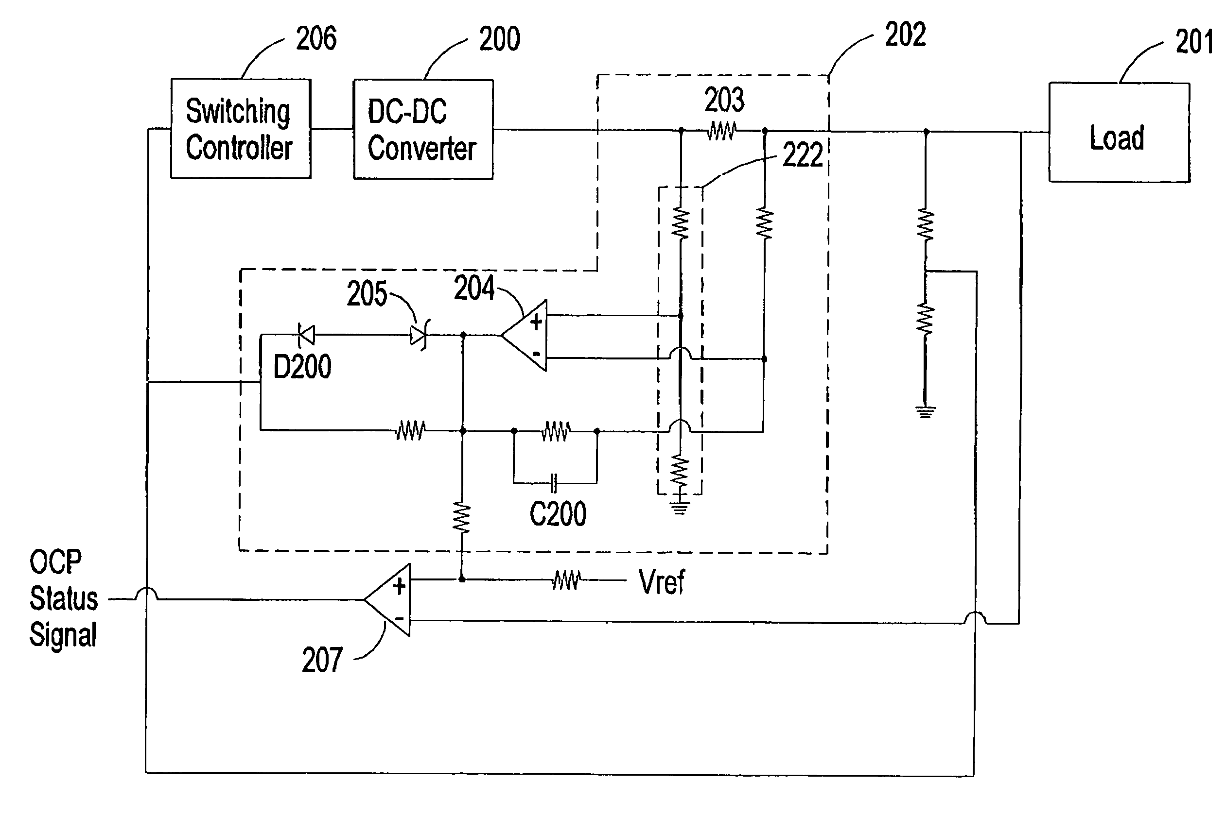
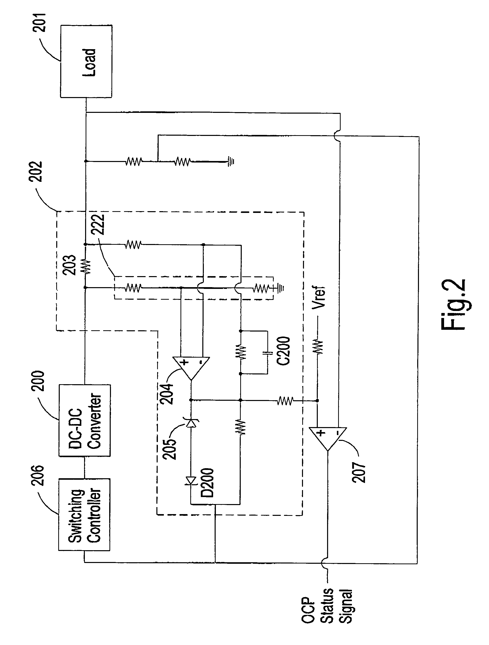
[0018]FIG. 2 illustrates a parallel power supply including an active droop current sharing circuit having a current limiting function according to a preferred embodiment of the present invention.

[0019]The parallel power supply of FIG. 2 includes a DC-DC converter 200 set to provide a predetermined voltage level to a common load 201 and share a proportion of the total load current with the other parallel power supplies. Also, the parallel power supply of FIG. 2 includes an active droop current sharing circuit 202 coupled between the DC-DC converter 200 and the common load 201. The active droop current sharing circuit 202 includes a current sensing resistor 203 placed in series with the common load 201 for developing a voltage proportional to the output current, so that the actual output voltage of the DC-DC converter 200 corresponds to the nominal output voltage of the DC-DC converter 200 minus the voltage drop across the current sensing resistor 203. Also, a current sensing amplifie...


PUM


Abstract

An active droop current sharing technique combined with current limiting function is employed in a parallel power supply. The parallel power supply is characterized with a current sensing amplifier that generates a current feedback signal representing a difference between a nominal output voltage and a fractional output voltage. The current sensing amplifier is coupled to a threshold level generator providing a threshold level defining a voltage level corresponding to a maximum allowed output current of the parallel power supply. If the voltage level of the current feedback signal exceeds the threshold level, the threshold level generator is turned on and the current feedback signal is coupled to a switching controller to adjust the output voltage of the power converter for properly addressing the current imbalance among plural parallel power supplies. Meanwhile, the threshold level generator induces a current to the current sense input of the switching controller, thereby limiting the output current of the power converter from exceeding the maximum allowed output current.

Description

FIELD OF THE INVENTION[0001]The present invention is related to a current sharing technique for use in a parallel power supply, and more particularly to an active droop current sharing circuit having a current limiting function for use in a parallel power supply.BACKGROUND OF THE INVENTION[0002]Switching power supply generally functions as a basic power supply unit for delivering electricity to satisfy the needs of electronic systems. For example, DC-DC converters are usually designed to convert a direct current (DC) voltage level to one or more different DC voltage levels that can meet a set of specifications.[0003]In practical operation, two or more DC-DC converters are connected in parallel to form a parallel power supply system when supplying power to an electronic system in consideration of load capacities. The parallel power supply system can provide a high-level redundancy for particular applications that requires power to be distributed with a high continuity and high reliab...

Claims


Application Information

Patent Timeline
Patent Type & Authority Patents(United States)
IPC IPC(8): G05F1/00
CPCH02J1/102H02M3/1584H02M3/285H02M1/32H02M2001/0009H02M1/0009
Inventor SAEUENG, SAKDAXU, MING CHUN
Owner DELTA ELECTRONICS (THAILAND) PUBLIC CO LTD
Why Eureka
Try Eureka