
Signal selector and combiner for broadband content distribution

a technology of broadband content and selector, applied in the direction of ghz frequency transmission, broadcast with distribution, television systems, etc., can solve the problems of complex circuit, increased complexity, and increased risk of multipath impairment in cable environment, and achieve the effect of eliminating the cross-point switch

Active Publication Date: 2009-06-02
ENTROPIC COMM INC
View PDF9 Cites 79 Cited by
  • Summary
  • Abstract
  • Description
  • Claims
  • Application Information

AI Technical Summary

Benefits of technology

"The present invention is a solution for selecting and combining transponder channels in an outdoor unit for transmitting signals to IRDs. The invention allows for the selection of one or more transponder channels from each LNB output, which can be translated to different frequencies and combined to form a composite signal. This composite signal can be transmitted over a single cable to a gateway unit or directly to the IRDs. The invention also allows for the communication of channel information through unoccupied regions of the frequency spectrum or wireless communication links. The invention reduces installation effort and allows for easy addition of IRDs without the need for a cross point switch. The combined transponder signal can occupy a predetermined region of the frequency spectrum, and can be shared with other signals transmitted on the distribution cable. The invention also allows for the use of a single or band stacked satellite signal."

Problems solved by technology

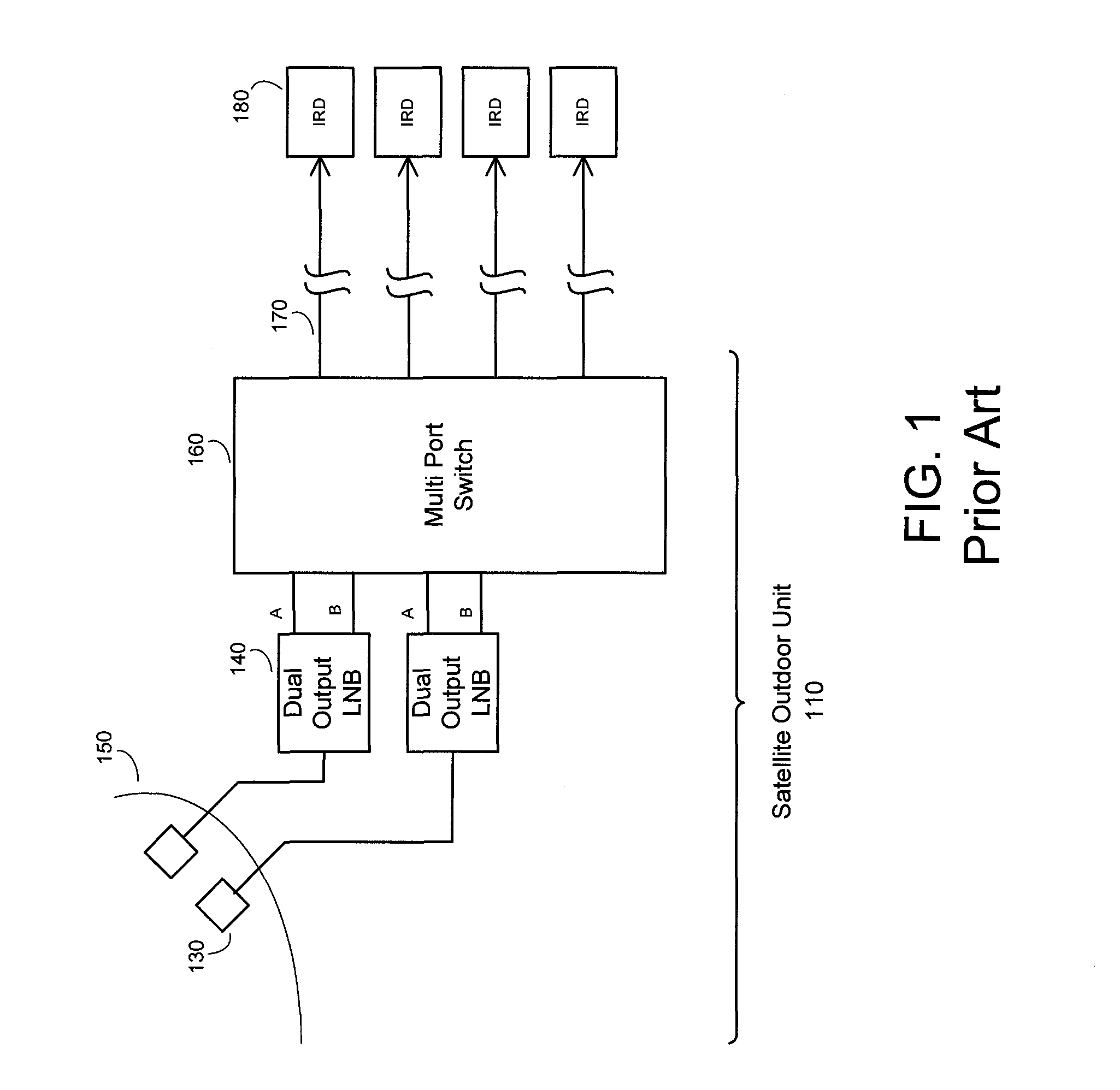
A problem with the conventional approach to connecting an outdoor unit to IRDs is that multiple cables are required to be run from the outdoor unit: one cable for each room where an IRD is located.
One problem with the Williams approach is the circuit complexity due to the 32 tuner paths required in the transmodulator.
For an increase in the number of satellite signals, this problem becomes more pronounced.
Williams discloses modulation using 128-QAM, which requires a higher signal to noise ratio (SNR) than QPSK and is it more susceptible to impairment from multipath present in a cable environment.
The problem with this approach is that the resulting bandwidth is very wide and becomes impractical when the number of LNB signals increases because each LNB output requires 500 MHz of bandwidth on the cable.

Method used


Image

  • Signal selector and combiner for broadband content distribution
  • Signal selector and combiner for broadband content distribution
  • Signal selector and combiner for broadband content distribution

Examples


Embodiment Construction

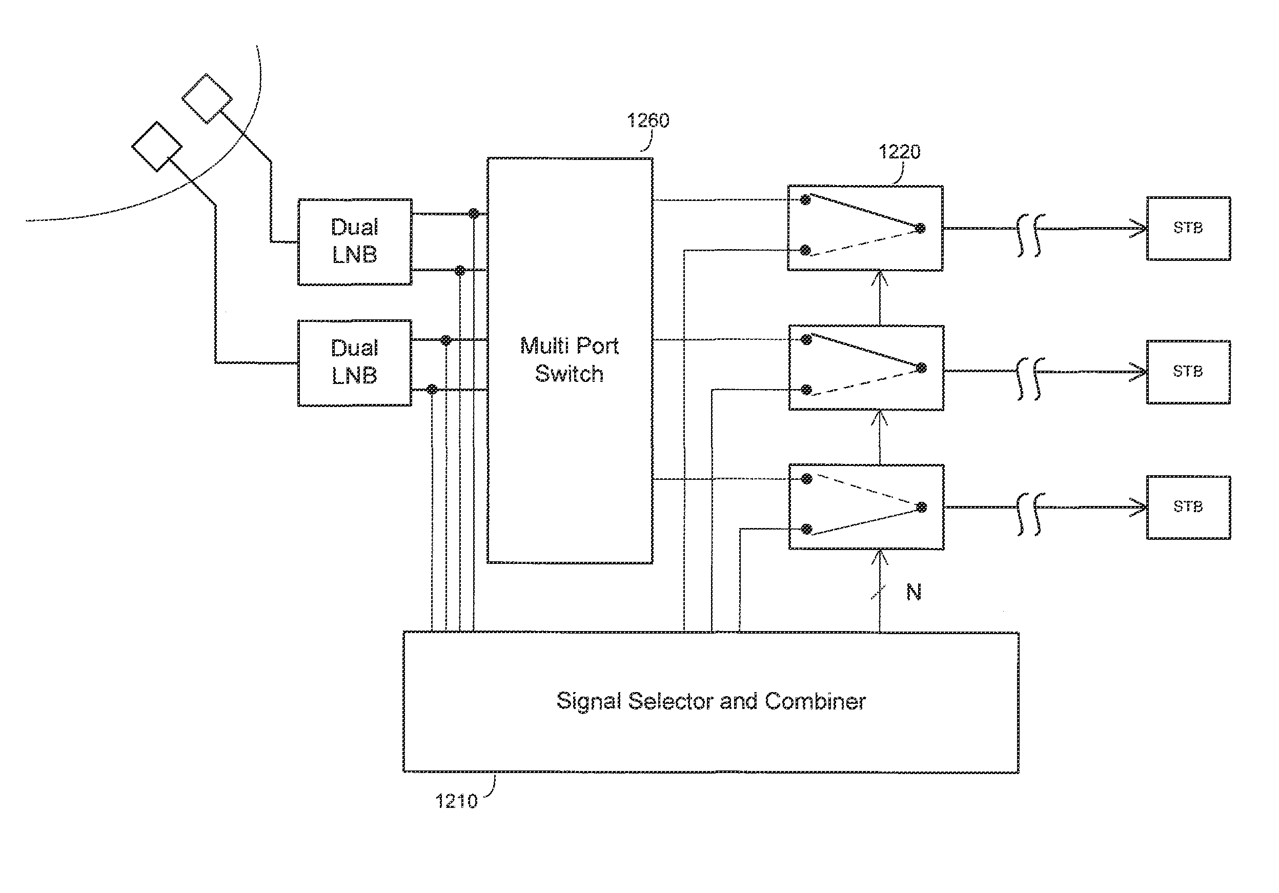
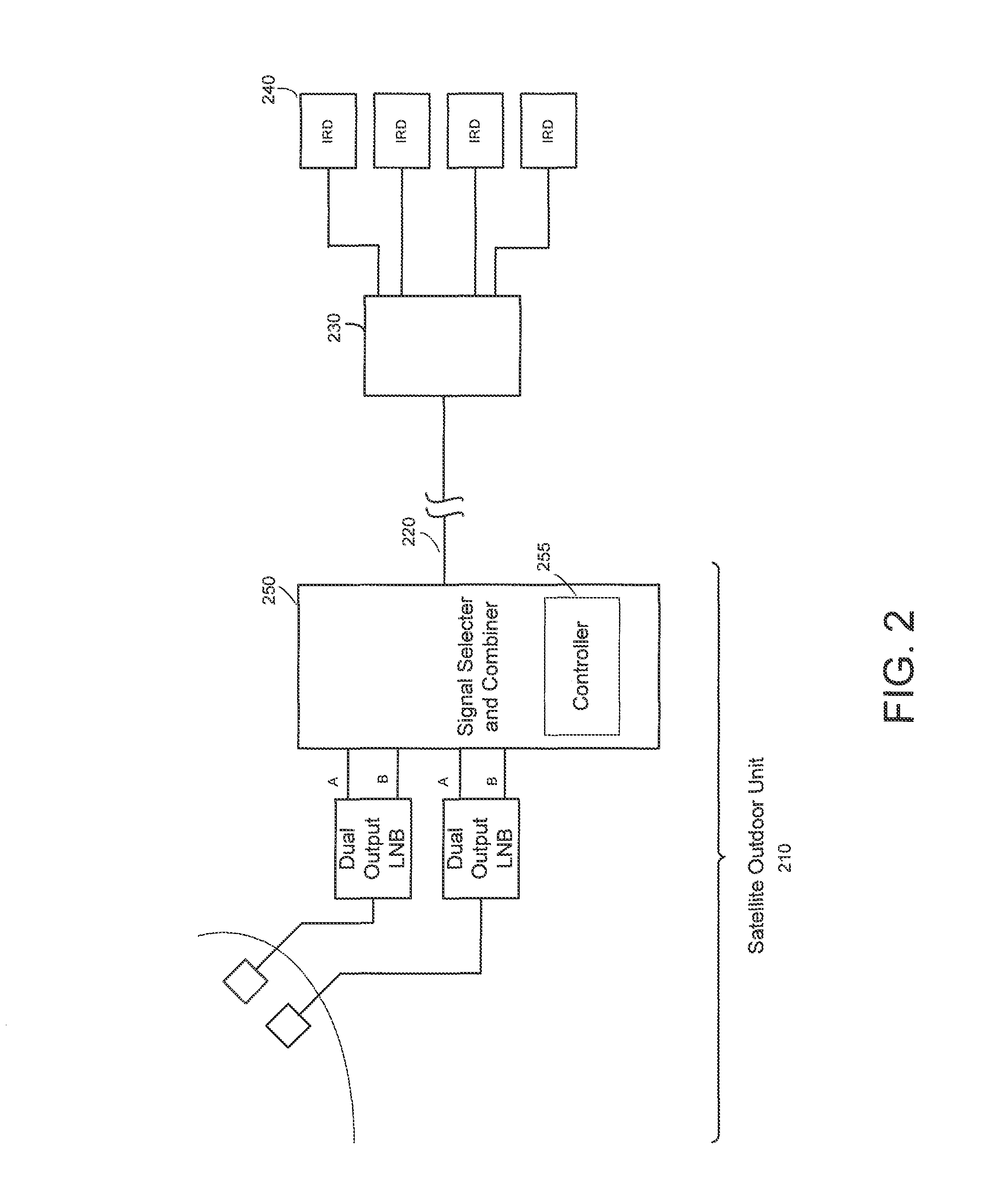
[0033]Referring to FIG. 2, a satellite TV installation according to the present invention is shown. Signal selector 250, part of satellite outdoor unit 210, extracts the needed transponder channels from each of the LNB outputs and combines the channels into one composite signal transmitted on cable 220. Gateway 230 receives the signals and provides distribution to the IRDs located in the building. Controller 255 is responsible for communicating channel map, control, and status information with gateway 230 and IRDs 240. Controller 255 also tunes filters and local oscillators in the signal selector and maintains the channel map specifying the assigned frequency slots for transponder channels. Alternatively, the channel map can be maintained by gateway 230.

[0034]Gateway 230 can be a simple power splitter / summer allowing the IRDs to connect directly to the cable. Gateway 230 would be located inside the home in a convenient location that allows connection to the IRDs 240. Gateway 230 is ...


PUM


Abstract

In a satellite receiving system, program channels are selected from one or more broadband signals and combined with other selected channels and transmitted from a first unit, for example an outdoor unit, to a second unit, for example a gateway, server, or set-top box, using a single cable. Channels can be selected by digitizing the broadband signal then digitally filtering to isolate the desired channels. The outputs of several LNBs can be selected and combined into one signal. Multiple set-top boxes can receive independent signals over a single cable from the outdoor unit.

Description

RELATED APPLICATIONS[0001]This application is a continuation of application Ser. No. 10 / 289,011 filed Nov. 6, 2002, with a projected issue date of Oct. 31, 2006 as U.S. Pat. No. 7,130,576, which claims priority to U.S. provisional patent application No. 60 / 345,965 filed Nov. 7, 2001 entitled “Signal Selector and Combiner for Broadband Content Distribution”; U.S. provisional patent application No. 60 / 333,722 filed Nov. 27, 2001 entitled “Signal Selector and Combiner for Broadband Content Distribution”; and U.S. provisional patent application No. 60 / 358,817 filed Feb. 22, 2002 entitled “Signal Selector and Combiner for Broadband Content Distribution”, each of which is incorporated herein by reference.BACKGROUND[0002]Referring to FIG. 1, a satellite receiver outdoor unit (ODU) 110 typically comprises a dish antenna 150, one or more antenna feed horns 130, one or more low noise amplifier and block down converters (LNB) 140, and an optional multiport cross point switch 160. Dish 150 coll...

Claims


Application Information

Patent Timeline
Patent Type & Authority Patents(United States)
IPC IPC(8): H04H20/71H04H1/00H04H40/90
CPCH04H40/90
Inventor GURANTZ, ITZHAKEL WARDANI, LADDLANDRY, MICHAEL
Owner ENTROPIC COMM INC
Learn More