
Heat pump liquid heater

a liquid heater and heat pump technology, applied in lighting and heating equipment, generators/motors, feed-through capacitors, etc., can solve the problems of reducing efficiency, reducing performance levels, and reducing the efficiency of the hplh system with a liquid pump

Inactive Publication Date: 2009-06-09
AIRGENERATE LLC
View PDF45 Cites 29 Cited by
  • Summary
  • Abstract
  • Description
  • Claims
  • Application Information

AI Technical Summary

Problems solved by technology

HPLH systems are attached with backup heating system like electrical elements or gas heaters if the HPLH system fails, has reduced performance levels, or if the demand for hot liquid surpasses the capacity of the HPLH system.
An HPLH system with a liquid pump adds to costs, complexity, and maintenance.
It also reduces efficiency because pumps need additional electrical energy to run.
An integrated HPLH system with a tank is limited to serve only new constructions or to replace old water heater tanks.
Such a system has a high cost of manufacturing and reduces the efficiency of heat transfer from the condenser coil to the liquid because the condenser coil is not in direct contact with the liquid.
This heat pump water heater has a limitation of heat transfer to the water because of the limited surface area provided by the cylindrical condenser exposed to the water.
The limited heat transfer reduces the efficiency of the system.
Therefore, the maximum heat transfer area is limited by these dimensions.
Another limitation of the heat pump water heater is the reduction in efficiency due to heating the returning refrigerant by entering hot refrigerant.
The heat gained in the return refrigerant is wasted.
Such a heat pump water heater is typically suited for a low capacity compressor but will significantly reduce the efficiency of a typical residential heat pump water heater.

Method used


Image

  • Heat pump liquid heater
  • Heat pump liquid heater
  • Heat pump liquid heater

Examples


first embodiment

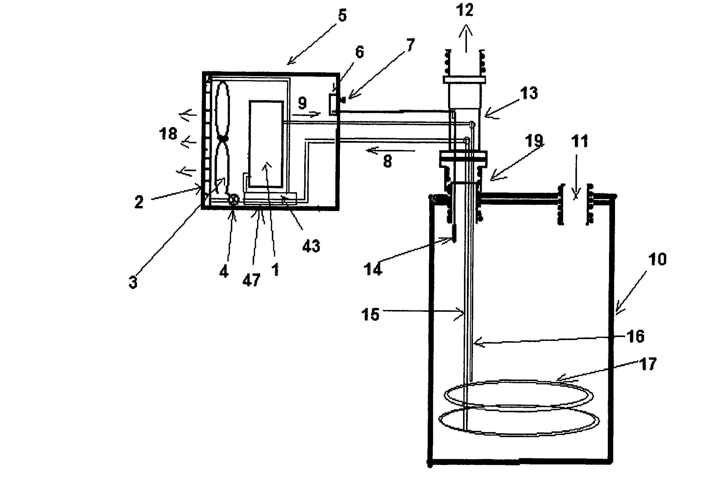
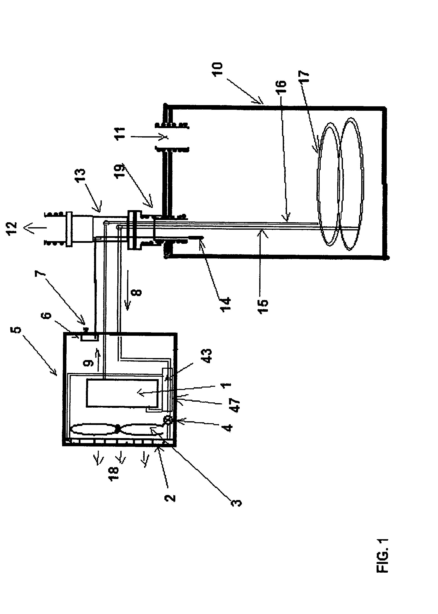
[0028]According to the present invention, a heat pump liquid heater for heating a liquid is disclosed. The HPLH comprises a heat pump; a liquid tank in heat communication with the heat pump, wherein the liquid tank comprises the liquid; and at least one metal condenser tube immersed into the liquid, and wherein the metal condenser tube forms at least one coil.

[0029]In a preferred embodiment, the metal condenser tube has a flattened double-tube configuration and a cross-section defined by concentric ovals such that at least a portion of the concentric ovals is in contact with one another thereby minimizing space between the flattened double-tubes.

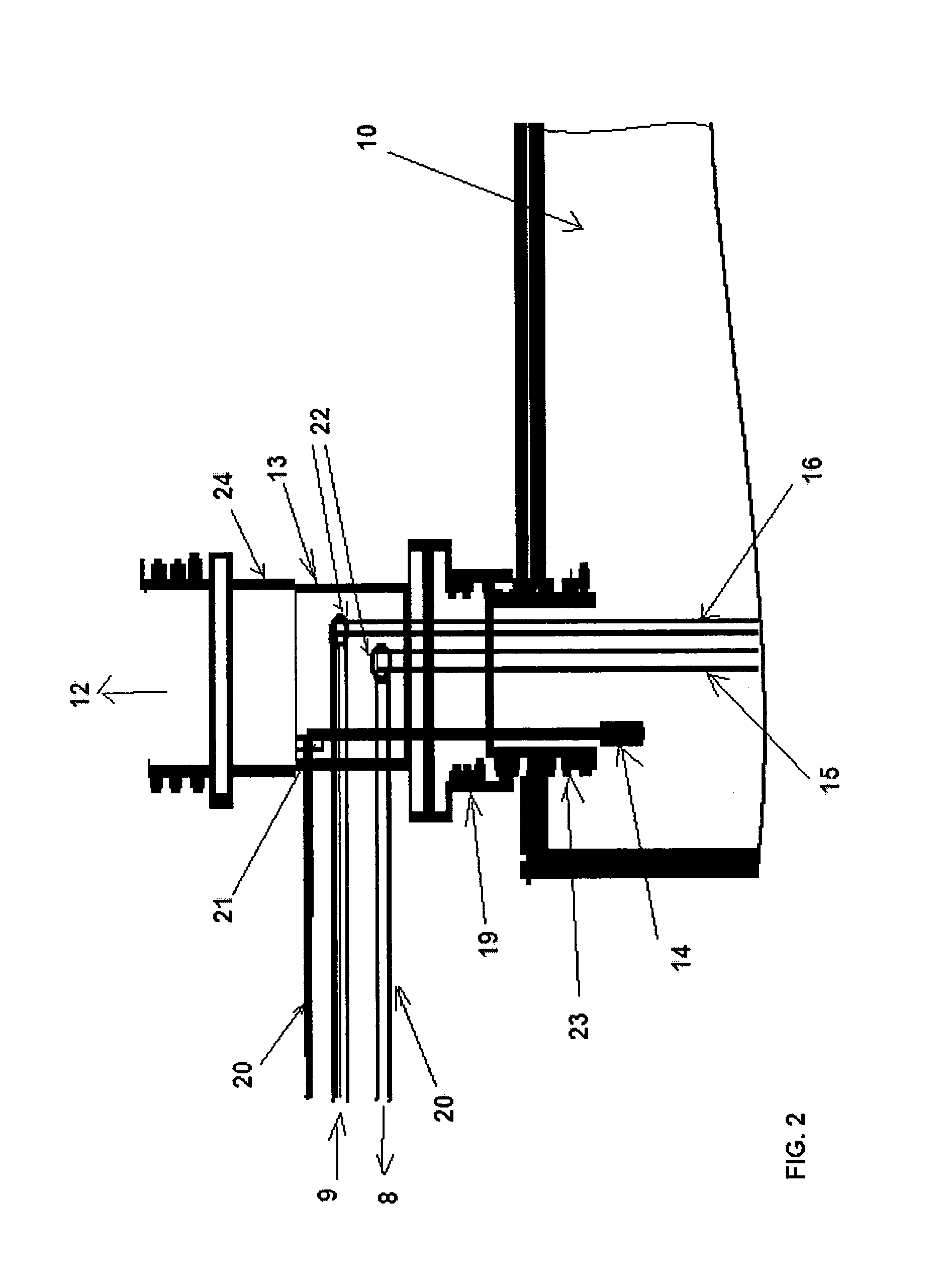
[0030]The metal condenser tube is connected to the heat pump and is immersed into the liquid via an adaptor assembly. The adaptor assembly is fixedly attached to the liquid tank. The adaptor assembly connects the heat pump and the liquid tank.

[0031]The metal condenser tube is a single continuous coiled tube. The metal condenser tube has a le...

second embodiment

[0035]According to the present invention, a method of heating a liquid is disclosed. The method of heating the liquid comprises supplying hot refrigerant from a heat pump liquid heater via at least one metal condenser tube; transferring heat from the hot refrigerant to the liquid in a liquid tank such that the liquid is heated to a predetermined temperature controlled by a thermostat, and wherein the metal condenser tube forms at least one coil.

[0036]In a preferred embodiment, the metal condenser tube has a flattened double-tube configuration and a cross-section defined by concentric ovals such that at least a portion of the concentric ovals is contact with one another thereby minimizing space between the flattened double-tubes. The heat pump comprises a tube-in-tube heat exchanger and a compressor, wherein the tube-in-tube heat exchanger recovers heat from refrigerant returning from the liquid tank and transfers the recovered heat to refrigerant going to the compressor thereby supe...

third embodiment

[0038] a heat pump liquid heater for heating a liquid is disclosed. The HPLH comprises a heat pump; a liquid tank in heat communication with the heat pump, wherein the liquid tank comprises the liquid; and at least one metal condenser tube immersed into the liquid, wherein the metal condenser tube comprises a refrigerant and is connected to the heat pump, and wherein the metal condenser tube is immersed into the liquid via an adaptor assembly, wherein the adaptor assembly comprises: a metal nipple fixedly attached to an opening in a liquid tank; a metal union fixedly attached onto the metal nipple; and a metal tube fixedly attached to the metal union, wherein the metal tube is adapted to receive at least one condenser tube and / or a thermostat bulb.

[0039]In a preferred embodiment, the metal condenser tube has a flattened double-tube configuration and a cross-section defined by concentric ovals such that at least a portion of the concentric ovals is in contact with one another thereby...


PUM


Abstract

A heat pump liquid heater for heating a liquid comprising: a heat pump; a liquid tank in heat communication with the heat pump, wherein the liquid tank comprises the liquid; and at least one metal condenser tube immersed into the liquid, wherein the metal condenser tube forms at least one coil. The metal condenser tube has a flattened double-tube configuration and a cross-section defined by concentric ovals such that at least a portion of the concentric ovals is in contact with one another thereby minimizing space between the flattened double-tubes. The heat pump comprises a tube-in-tube heat exchanger and a compressor, wherein the tube-in-tube heat exchanger recovers heat from refrigerant returning from the liquid tank and transfers the recovered heat to refrigerant going to the compressor thereby superheating the refrigerant.

Description

FIELD OF THE INVENTION[0001]The present invention is related to heat pump liquid heating systems and methods of heating a liquid.BACKGROUND OF THE INVENTION[0002]A Heat Pump Liquid Heater (“HPLH”) uses a refrigeration system to extract heat from the surrounding environment to heat a liquid. An HPLH system typically consumes less than half the energy relative to a conventional, electric-resistance or gas burner liquid heater. An HPLH system is based on a reverse refrigeration cycle with the HPLH system using an electrical compressor to compress the refrigerant to a liquid state which is at a high pressure and temperature. The refrigerant at high temperature and pressure transfers heat to a liquid and then goes though an expansion process where the temperature and pressure of the refrigerant are reduced to form a low temperature refrigerant. The low temperature refrigerant passes through an evaporator absorbing heat from the surrounding air and converts into a gaseous state. The gaseo...

Claims


Application Information

Patent Timeline
Patent Type & Authority Patents(United States)
IPC IPC(8): F25B27/00F24D18/00
CPCF24H4/04F25B39/04F28D7/024F28F1/02F28F9/26F28F1/003F25B2339/047Y02B30/52F24H2240/01F24D18/00F24D2103/13F24D2101/40F25B27/00H01G4/35F25B49/00F25B13/00
Inventor SINHA, SUNIL KUMARDEYSARKAR, ASOKE
Owner AIRGENERATE LLC
Learn More