
System and method for management of a ground obstacle display

a technology for managing systems and obstacles, applied in the direction of underwater vessels, non-deflectible wheel steering, navigation instruments, etc., can solve the problems of flight crews not being able to properly observe the obstacle on the tad, other potentially hazardous terrain or man-made obstructions still exist, and the coded ground obstruction symbol

Active Publication Date: 2009-06-23
HONEYWELL INT INC
View PDF10 Cites 8 Cited by
  • Summary
  • Abstract
  • Description
  • Claims
  • Application Information

AI Technical Summary

Benefits of technology

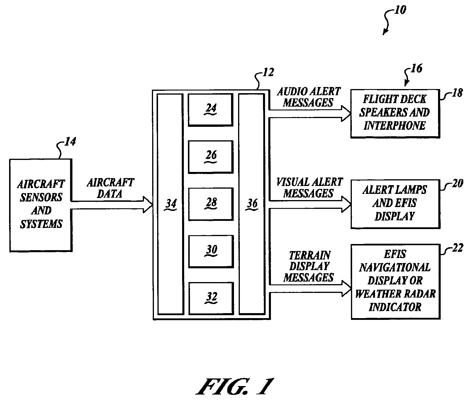
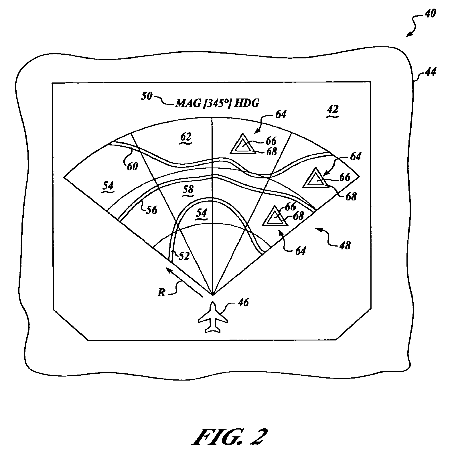
The patent describes a system for displaying information about ground obstacles to an aircraft pilot. The system uses data from sensors on the aircraft to create a virtual representation of the ground that includes information about any obstacles. This representation is displayed on a screen in front of the pilot. The system can also change the appearance of the virtual obstacles to match the terrain elevations, making it easier for the pilot to see the obstacles in relation to the ground. Overall, this system helps improve safety for piloted aircraft by providing valuable information about potential hazards on the ground.

Problems solved by technology

Although present ground proximity warning systems significantly enhance the safety of flight, other potentially hazardous terrain or man-made obstructions nevertheless exist.
Although the display of ground obstacles on a TAD constitutes a significant contribution to flight safety, various potential drawbacks may nevertheless exist.
For example, the symbol associated with the ground obstacle may not be readily distinguishable from a terrain depiction on the TAD, so that a flight crew may fail to properly observe the obstacle on the TAD.
In a further example, a color associated with a terrain depiction of a selected geographical location may not permit a color-coded ground obstruction symbol to be properly distinguished.

Method used


Image

  • System and method for management of a ground obstacle display
  • System and method for management of a ground obstacle display
  • System and method for management of a ground obstacle display

Examples


Embodiment Construction

[0012]The present invention relates to ground proximity warning systems and methods. Many specific details of certain embodiments of the invention are set forth in the following description and in FIGS. 1 through 4 to provide a thorough understanding of such embodiments. One skilled in the art, however, will understand that the present invention may have additional embodiments, or that the present invention may be practiced without several of the details described in the following description. In the discussion that follows, it is understood that “color” describes a property of visible electromagnetic radiation that may be described in terms of dominant wavelength, luminance, and purity. Accordingly, visible electromagnetic radiation having a red color property corresponds to a range of wavelengths between approximately about 630 to 760 nanometers (nm), while visible radiation having a green color property corresponds to a range of wavelengths between approximately about 490 to 570 ...


PUM


Abstract

Systems and methods for managing a visual display in a ground proximity warning system. In one embodiment, a system includes at least one aircraft sensor system operable to acquire aircraft data and a ground proximity warning computer coupled to the aircraft sensor system that is operable to process the aircraft data to generate ground proximity warning data corresponding to a sensed ground obstruction. An indicating system includes at least one visual display device that is operable to display terrain elevations and to display a visual symbol corresponding to at least one of the ground obstructions, wherein at least one of the computer and the visual display device is controllable to selectively alter an appearance of the visual symbol relative to the terrain elevations.

Description

CROSS-REFERENCE TO RELATED APPLICATIONS[0001]This application claims benefit of U.S. Provisional Application Ser. No. 60 / 674,223, filed Apr. 21, 2005, which is hereby incorporated by reference.BACKGROUND OF THE INVENTION[0002]Ground proximity warning systems (GPWS) are known and are presently installed on a wide variety of aircraft. Such systems generally provide both aural and visual warnings of inadvertent aircraft descent during flight operations. For example, a GPWS may be configured to detect an excessive loss of altitude during a landing procedure, following a take-off, or during a go-around following a missed landing approach. The GPWS also advantageously provides aural and visual warnings of potential terrain collisions during controlled flight over relatively high altitude terrain. In general, the GPWS detects an altitude loss by computing a barometric altitude (MSL), a geometric altitude, and / or a descent rate based upon changes in the barometric pressure. In cases where t...

Claims


Application Information

Patent Timeline
Patent Type & Authority Patents(United States)
IPC IPC(8): G08G5/04G01S13/94G01S13/935
CPCG01C5/005
Inventor KHATWA, RATAN
Owner HONEYWELL INT INC
Learn More