Salicide process utilizing a cluster ion implantation process
a cluster ion and implantation technology, applied in the field of salicide process, can solve the problems of time-dependent dielectric breakdown (tddb) failure, junction leakage, and flawed titanium silicide process, and achieve the effect of low resistivity and preferable quality
- Summary
- Abstract
- Description
- Claims
- Application Information
AI Technical Summary
Benefits of technology
Problems solved by technology
Method used
Image
Examples
first embodiment
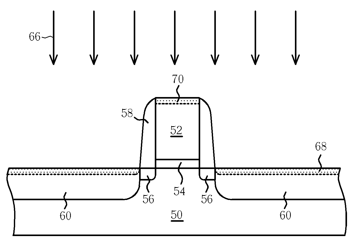
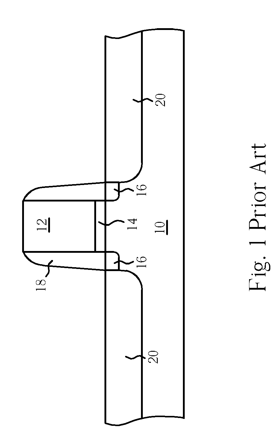
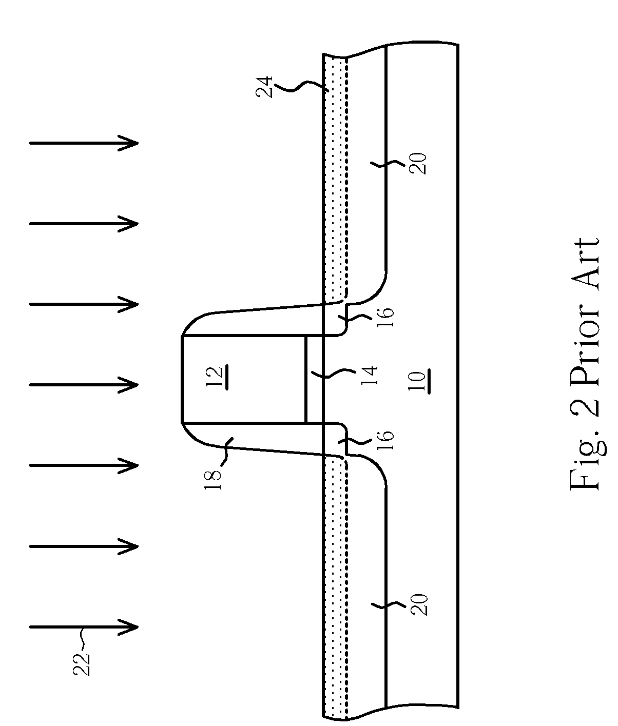
[0023]With reference to FIGS. 6-11, FIGS. 6-11 are schematic diagrams of a salicide process according to the present invention. As shown in FIG. 6, a semiconductor substrate 50 is provided, and a gate electrode 52 and a gate insulating layer 54 are formed on the semiconductor substrate 50, wherein the semiconductor substrate 50 may be a silicon substrate. Then, a first ion implantation process is performed to form source / drain extensions 56 in the semiconductor substrate 50 at two sides of the gate electrode 52.
[0024]Referring to FIG. 7, a nitride layer (not shown) is deposited on the semiconductor substrate 50. Thereafter, a dry etching process or an anisotropic etching process is performed to removing portions of the nitride layer so as to form spacers 58 on the sidewall of the gate electrode 52 and the gate insulating layer 54. Next, the gate electrode 52 and the spacers 58 are utilized as masks to perform a second ion implantation process for forming the source / drain regions 60 ...
second embodiment
[0030]Please refer to FIGS. 12-16, which are schematic diagrams of a method of forming a metal-oxide semiconductor (MOS) transistor according to the present invention. As shown in FIG. 12, a gate electrode 112 is formed on a substrate 110 with a gate insulating layer 114 interposed therebetween. A lining layer 118, preferably a silicon dioxide layer, is then deposited over the top surface and sidewalls of the gate electrode 112, and on the exposed surface of the substrate 110. An ion implantation process is carried out to implant dopant into the substrate 110 so as to form shallow junction source / drain extensions 116.
[0031]As shown in FIG. 13, a layer of silicon nitride (not shown) is deposited on the lining layer 118. An anisotropic dry etching is then carried out to etch the silicon nitride layer and the lining layer 118, thereby forming a pair of silicon nitride spacers 120 and an L-shaped liner layer 118′ on the sidewalls of the gate electrode 112. Subsequently, a high-dosage io...
third embodiment
[0034]FIGS. 17-21 are schematic diagrams of a method of forming a MOS transistor according to the present invention. Referring to FIG. 17, a substrate 200 such as P-type substrate is provided. Then, a gate oxide layer 202 functioning as a gate insulating layer and a polysilicon gate 204 are formed on the substrate 200. The gate oxide layer 202 is provided by defining an oxide layer formed by thermal oxidation. The polysilicon gate 204 is deposited by low pressure chemical vapor deposition (LPCVD) and is doped to render the polysilicon conductive.
[0035]Next, the substrate 200 is doped to form source / drain regions 210 in the substrate 200 and to define a channel of a MOS transistor. The formation process of the source / drain regions 210 may comprise a step of implanting an impurity, for example, phosphorus with low dosage, through the polysilicon gate 204 as a mask to form lightly doped source / drain regions 206, a step of depositing a second oxide layer on the entire surface of the dev...
PUM
| Property | Measurement | Unit |
|---|---|---|
| depth | aaaaa | aaaaa |
| depth | aaaaa | aaaaa |
| depth | aaaaa | aaaaa |
Abstract
Description
Claims
Application Information
 - R&D
- Intellectual Property
- Life Sciences
- Materials
- Tech Scout
- Unparalleled Data Quality
- Higher Quality Content
- 60% Fewer Hallucinations
Browse by: Latest US Patents, China's latest patents, Technical Efficacy Thesaurus, Application Domain, Technology Topic, Popular Technical Reports.
© 2025 PatSnap. All rights reserved.Legal|Privacy policy|Modern Slavery Act Transparency Statement|Sitemap|About US| Contact US: help@patsnap.com


