Chopper knife for a straw chopper

a straw chopper and chopper blade technology, which is applied in the field of chopper blades for straw choppers, can solve the problems of shortening reducing the service life of the chopper blade, and requiring a large number of chopper blades

Active Publication Date: 2009-07-07
DEERE & CO
View PDF22 Cites 13 Cited by
  • Summary
  • Abstract
  • Description
  • Claims
  • Application Information

AI Technical Summary

Benefits of technology

[0007]It is an object of the present invention to provide a chopper knife for a straw chopper having advantageous aerodynamics and a long service life.
[0009]The asymmetry of the two ground faces of a cutting edge makes it possible to separate the apices of the cutting edges from the center plane of the chopper knife in order to improve the aerodynamic effect of the cutting edges. However, the apices of the cutting edges may also lie on the center plane of the chopper knives, in which case the ground faces are shaped differently in order to effect the profile of a wing section. Since two ground faces are provided, the apices are also separated from the side faces such that the bending moments generated when the chopper knives come in contact with the material to be chopped are simultaneously reduced.
[0011]In order to increase the friction resistance on the outer end face of the chopper knife in the chopping mode, it is proposed to provide the outer end face with a radius in the plane defined by the side faces. This measure makes it possible to extend the service life of the chopper knife since the induced air resistance is reduced due to the elimination of sharp edges. In addition, a superior lateral distribution of the straw is effected since a larger projected end face is formed in the region of the greatest circumferential speed. The radius preferably corresponds at least approximately to the inside radius of the housing that accommodates the straw chopper rotor.
[0012]The radii on the apices of the cutting edges are advantageous because they prevent a premature separation of the air flow. This results in an improved air flow through the straw chopper and the service life of the chopper knives is simultaneously extended because the geometric notch effect is reduced.
[0013]In a preferred embodiment, the cutting edges include notches. It is preferred to arrange the serration in the direction of the respectively longer ground face of each cutting edge. In this case, the geometric notch is located in the region of the neutral bending axis of the chopper knife such that the stress peaks in the notch root due to bending stresses are reduced. This increases the fatigue strength of the chopper knife. In another embodiment that also performed well in empirical tests, the serrations are arranged in the direction of the respectively shorter ground face of each cutting edge.
[0015]The chopper knives (preferably all chopper knives of a rotor) are usually mounted in pairs on suitable brackets of the rotor, namely in pendular fashion. In this respect, it is practical to arrange the sides of the chopper knives such that the respectively longer ground faces point toward one another. The aerodynamic effect of the ground faces causes a negative pressure to be generated on the faces of the chopper knives which point toward one another and a positive pressure to be generated on the outer sides. Thus, the chopper knives stabilize one another.

Problems solved by technology

During the chopping process, this geometry leads to bending moments in the chopper knife, which cause vibrations that reduce the service life due to fatigue fractures.
Aerodynamic influences also cause bending moments to be generated in chopper knives with this geometry, where these bending moments generate vibrations that shorten the service life of the chopper knife.
In addition, the continuously varying grinding configuration of the chopper knives has the disadvantage that a large number of different chopper knives is required.
This negatively affects the manufacture, shipping and storage of such chopper knives.

Method used


Image

  • Chopper knife for a straw chopper
  • Chopper knife for a straw chopper
  • Chopper knife for a straw chopper

Examples


Embodiment Construction

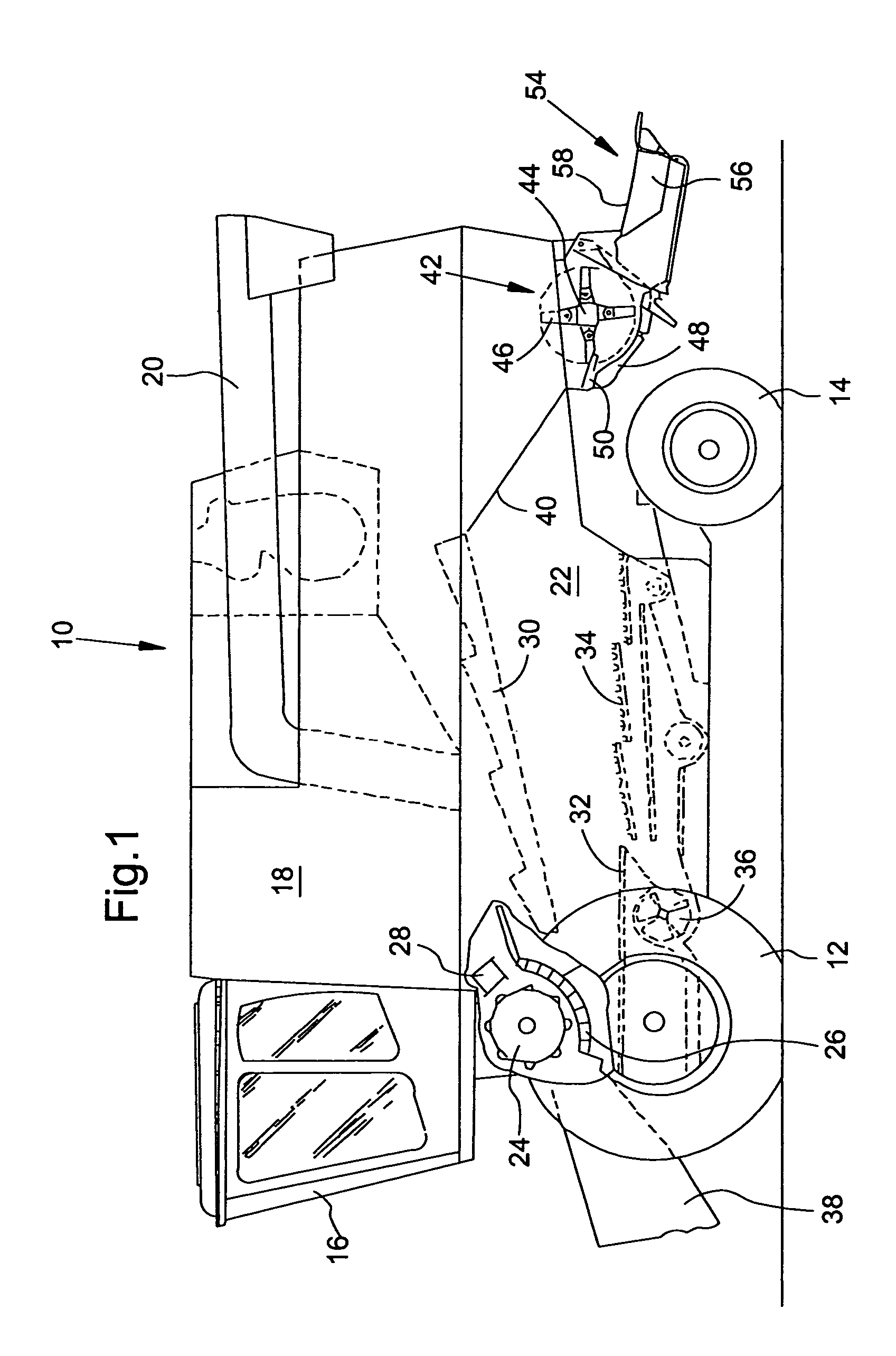
[0025]FIG. 1 shows a harvesting machine 10 in the form of a combine that is supported on driven front wheels 12 and steerable rear wheels 14. The harvesting machine 10 comprises and operators cab 16, from which the combine can be controlled by a driver. A grain bin 18 is located behind the operators cab 16 and is provided with a discharge auger 20 for discharging harvested crop material from the grain bin 18. A frame 22 supports the grain bin 18, as well as a threshing cylinder 24, a threshing concave 26 and a beater 28. The threshing cylinder 24, the threshing concave 26 and the beater 28 are used to separate the harvested crop into larger and smaller components. The threshed crop material is also separated on adjoining straw walkers 30, as well as on a grain pan 32. The threshed and separated crop is cleaned on sieves 34 by an air blast passing upwardly through the sieves 34 by a cleaning fan 36. The cleaned crop is ultimately transported into the grain bin 18. The larger non-grai...


PUM


Abstract

A chopper knife for a straw chopper has two side faces defining cutting edges. Each cutting edge is made up of two asymmetrical ground faces. The side faces are arranged at an angle with respect to the side faces. The cross section of the chopper knife in the region of the cutting edges is mirror-symmetric to the center plane of the chopper knife.

Description

FIELD OF THE INVENTION[0001]The present invention is directed to a chopper knife for a straw chopper having a cutting edge with two faces that are asymmetrical.BACKGROUND OF THE INVENTION[0002]EP 0 277 129 B discloses a straw chopper that comprises a housing with opposing knives and a rotatable rotor arranged therein. Pairs of chopper knives are suspended in pendular fashion from the rotor, wherein the leading edges of the chopper knives are provided with beveled faces that form sharp edges. In order to control the direction of distribution and the dispersion width of the chopped straw, the beveled faces of the suspended chopper knife pairs are arranged in an alternating configuration such that the beveled faces either point toward or away from each other. Thus, the chopper knives have a trapezoidal or rhomboidal cross section.[0003]During the chopping process, this geometry leads to bending moments in the chopper knife, which cause vibrations that reduce the service life due to fat...

Claims


Application Information

Patent Timeline
Patent Type & Authority Patents(United States)
IPC IPC(8): A01D34/42A01F12/40B02C18/18
CPCB02C18/18A01F12/40
Inventor PRIESNITZ, RICOVEIT, PETER
Owner DEERE & CO
Why Eureka
Try Eureka