Clamp

a clamp and clamping technology, applied in the field of clamps, can solve the problems of time-consuming and/or laborious process of tightening or loosening the rack, prone to loosening of the tightened bolt b>5/b>, and achieve the effect of preventing accidental loosening or theft of the clamp

Inactive Publication Date: 2009-07-07
MASTER LOCK CO INC
View PDF11 Cites 30 Cited by
  • Summary
  • Abstract
  • Description
  • Claims
  • Application Information

AI Technical Summary

Benefits of technology

[0006]The present application relates to a clamp for securing an item to a structure. According to one aspect of the application, a clamp may be adapted to provide a quick clamping mechanism that does not require multiple rotations of a bolt or other fastener to securely clamp the item. According to another aspect of the application, a clamp may be adapted to provide a uniform clamp load to an item secured between two plates when the plates are skewed at an angle with respect to each other. According to yet another aspect of the application, a clamp may be adapted to be locked in the clamped condition, thus preventing accidental loosening of the clamp or theft of the secured item.

Problems solved by technology

While these or other locks may be sufficient to secure an item to a stationary structure, such a locking arrangement is often inadequate when securing the item to a vehicle, as movement of an item loosely attached to a moving vehicle may cause damage to the item and cause safety hazards to the driver and to others.
However, the process of tightening or loosening the rack I may be time consuming and / or strenuous, as numerous rotations of the bolt 5 may be necessary to tightly clamp the crossbars A, B. Also, the tightened bolt 5 may be susceptible to loosening as a result of vibrations experienced when the vehicle is driven.
Further, when clamping an item on only one side of the rack 1, the plates 2, 3 may skew, resulting in an uneven clamping force or difficulty in tightening the rack 1.
Still further, the clamping rack 1 illustrated in FIG. 1 does not offer a lockout feature, thus presenting a risk of theft.

Method used


Image

  • Clamp
  • Clamp
  • Clamp

Examples


Embodiment Construction

[0015]This Detailed Description of the Invention merely describes embodiments of the invention and is not intended to limit the scope of the claims in any way. Indeed, the invention as described is broader than and not limited by the preferred embodiments, and the terms used have their full ordinary meaning.

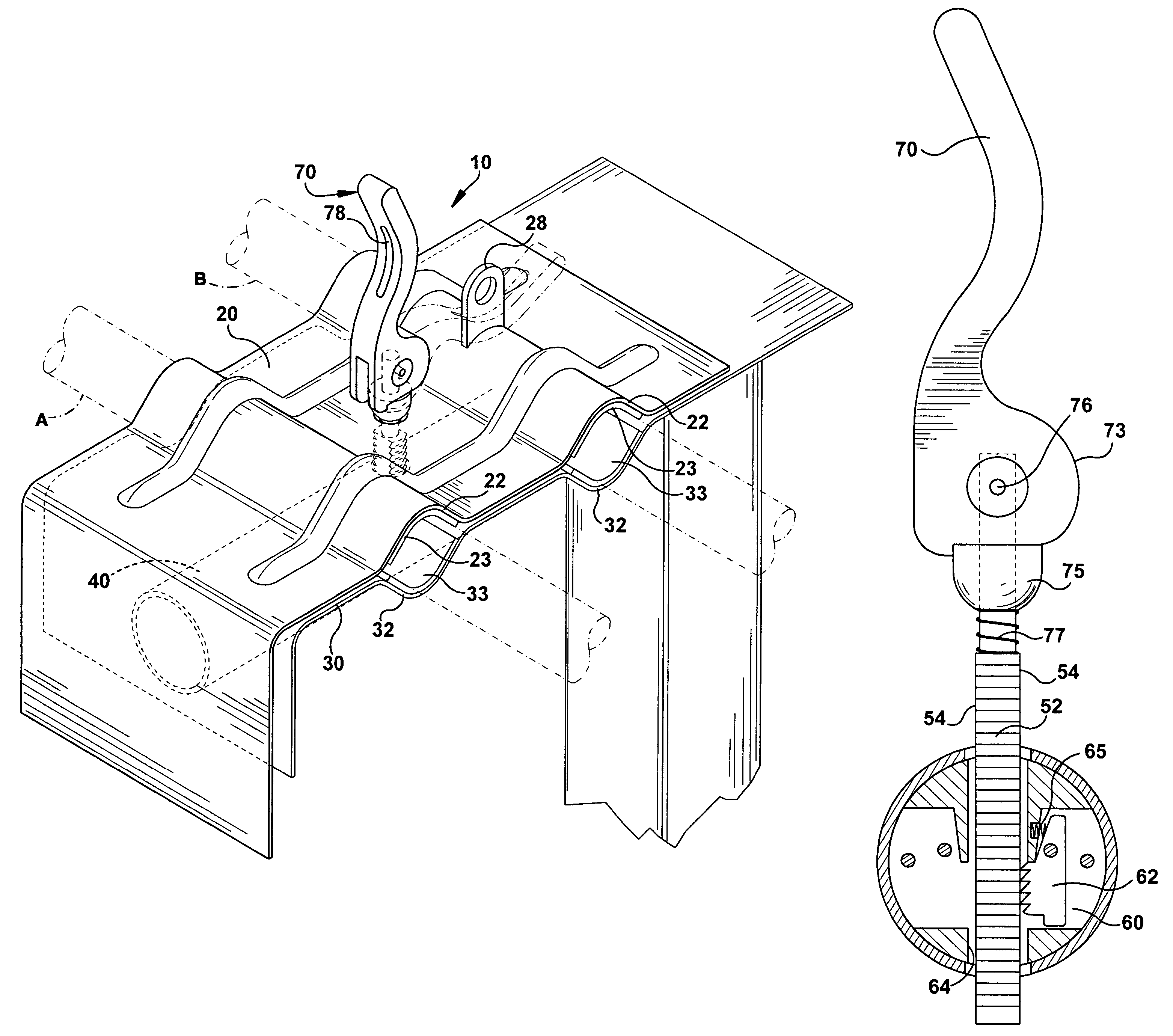
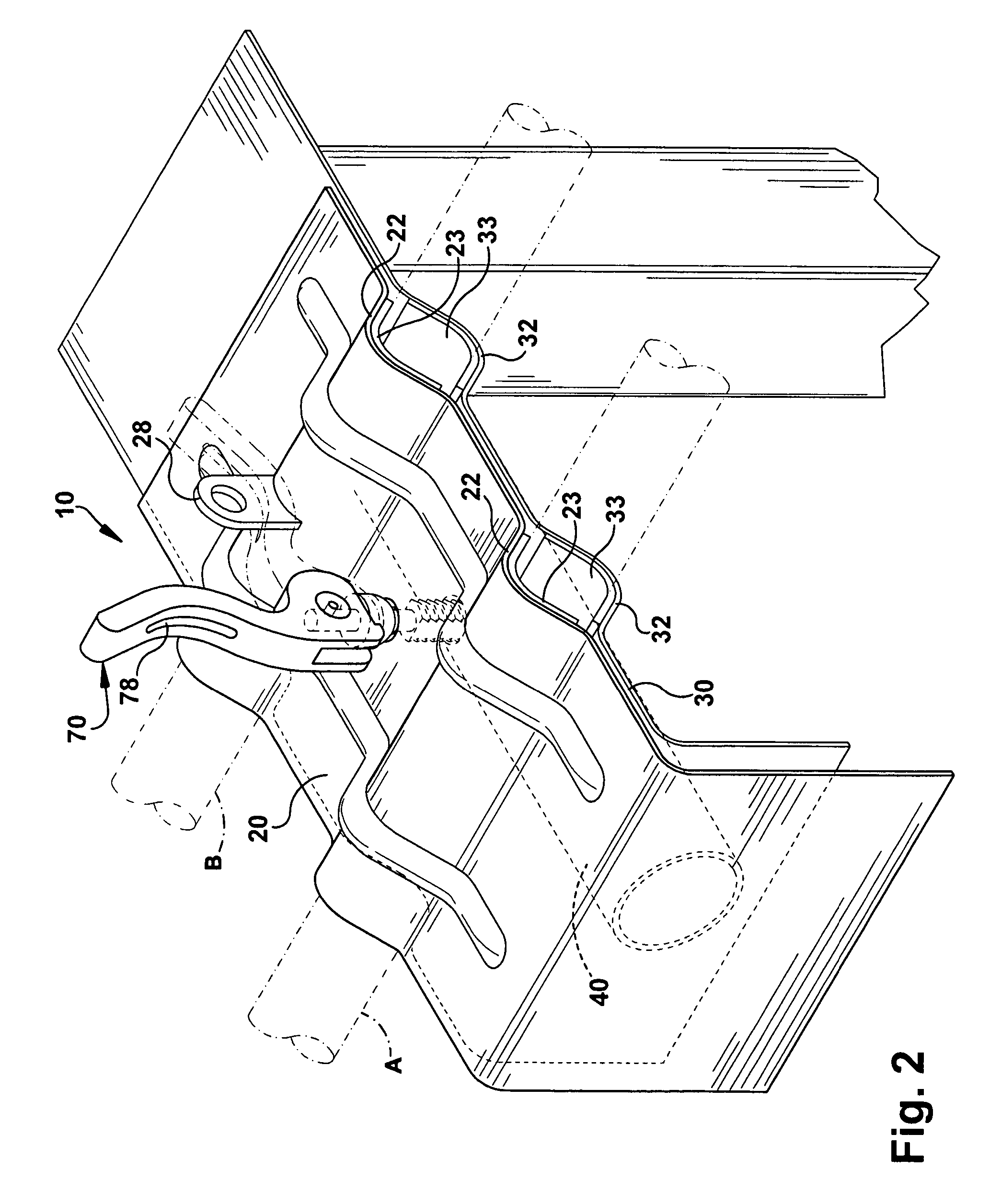
[0016]FIGS. 2-6 illustrate a clamp or clamping arrangement 10 according to an exemplary embodiment of the invention, adapted for use in securing one or more bicycles to a truck or automobile. It should be understood that features of the present invention may be applied to securing a wide variety of items to many types of stationary or vehicle mounted racks or structures.

[0017]In one embodiment, a clamping arrangement may include first and second clamping members between which one or more items may be clamped. The clamping members may take many different forms or configurations to accommodate the item or items to be clamped. In the illustrated embodiment of FIGS. 2 and 3, the clam...


PUM


Abstract

A clamp for securing an item includes a locking rod, first and second clamping members, and a retainer. The locking rod includes an elongated body and a locking member connected to a first end of the elongated body. The locking member is movable between a clamping position and a release position. The first clamping member includes a first opening for receiving a second end of the locking rod body therethrough. The second clamping member is adapted to align with the first clamping member to receive the item therebetween. The retainer is connected to the second clamping member and includes a second opening for receiving the second end of the locking rod body and an interlocking feature for engaging a corresponding interlocking feature on the locking rod body when the locking rod body is in a first rotational position. When the item is positioned between the first and second clamping members and the locking rod is inserted through the first opening and into the second opening and oriented in the first rotational position, moving the locking member from the release position to the clamping position tightens the first and second clamping members into clamping engagement with the item.

Description

CROSS REFERENCE TO RELATED APPLICATIONS[0001]This application claims the benefit of U.S. Provisional Patent Application No. 60 / 691,922, filed Jun. 17, 2005, the entire disclosure of which is hereby incorporated by reference.FIELD OF THE INVENTION[0002]The present application relates to a clamp and more specifically to a clamp featuring quick clamping and releasing features for use in securing an item.BACKGROUND OF THE INVENTION[0003]Conventional cable locks and U-bar locks are often used to secure an item, such as, for example, a bicycle, to a structure, such as a bicycle rack or sign post. While these or other locks may be sufficient to secure an item to a stationary structure, such a locking arrangement is often inadequate when securing the item to a vehicle, as movement of an item loosely attached to a moving vehicle may cause damage to the item and cause safety hazards to the driver and to others.[0004]Racks have been provided for mounting on cars, trucks and buses, to provide a...

Claims


Application Information

Patent Timeline
Patent Type & Authority Patents(United States)
IPC IPC(8): A47B96/06B60R9/00E04G3/00
CPCF16B2/185F16B7/0433F16B37/0857F16B35/06F16B37/085F16B12/40
Inventor ELLIOTT, JOESCOTT, FRANK
Owner MASTER LOCK CO INC
Why Eureka
Try Eureka