Connector

a technology of connecting rods and connectors, applied in the direction of connection, electrical apparatus, coupling device connection, etc., can solve the problems of limited movement of the terminal retaining member, metal terminals may be withdrawn from the housing, and adversely affected the manufacture of wire harnesses, etc., to achieve sufficient retaining force and engagement.

Inactive Publication Date: 2009-07-07
YAZAKI CORP
View PDF6 Cites 27 Cited by
  • Summary
  • Abstract
  • Description
  • Claims
  • Application Information

AI Technical Summary

Benefits of technology

[0015]This invention has been made in view of the above circumstances, and an object of the invention is to provide a connector in which the efficiency of an assembling operation, the efficiency of a maintenance operation, etc., are enhanced, and also a sufficient retaining force can be secured with a compact design, and further a half-inserted condition of a metal terminal can be detected. Another object is to provide a connector in which only a necessary metal terminal can be easily removed.

Problems solved by technology

Furthermore, when the metal terminal is kept in a half-fitted condition relative to the housing, the movement of the terminal retaining member is limited so that such a half-fitted condition can be detected.
Therefore, there is a fear that the metal terminal may be withdrawn from the housing (In the case of the multi-pole connector, the metal terminals often are not mounted at one time, and the terminal retaining member is kept in a provisionally-retained condition, and in this condition the assembling process shifts from one step to another.
Therefore, in such a situation in which the metal terminal may be withdrawn from the housing, the manufacture of the wire harness will be adversely affected.
Furthermore, in the conventional technique disclosed in Patent Literature 1, the movement of the metal terminal in the withdrawing direction is not prevented as described above, and therefore in the case of the multi-pole connector, when the terminal retaining member is shifted from the completely-retained condition to the provisionally-retained condition, there is a fear that even those metal terminals, for example, which are not required for maintenance, may also be withdrawn from the housing (that is, the efficiency of the maintenance operation is low).
Therefore, there is encountered a problem that the metal terminal itself has an increased size because of the formation of these projecting portions.
The increased size of the metal terminal leads to a problem that the connector is also increased in size.
This clearance may invite a disadvantage that the metal terminal may be inclined, and if the metal terminal is thus inclined, a retaining force provided by the primary retaining is lowered.
When withdrawing such inclined metal terminal from the housing, for example, for maintenance purposes, there is encountered a problem that the inclined metal terminal is caught by the housing, and therefore can not be withdrawn from the housing.
Furthermore, in the conventional technique disclosed in Patent Literature 2, the housing need to have the large space for receiving the metal terminals as described above, and therefore there is encountered a problem that the connector is increased in size.
Furthermore, in the conventional technique disclosed in Patent Literature 2, the connector is constructed such that the metal terminal is pushed up by the terminal retaining member as described above, and therefore in the case of the multi-pole connector, all of the metal terminals must be pushed up at one time, and therefore there is encountered a problem that the efficiency of the assembling operation is adversely affected.

Method used


Image

  • Connector
  • Connector
  • Connector

Examples


Embodiment Construction

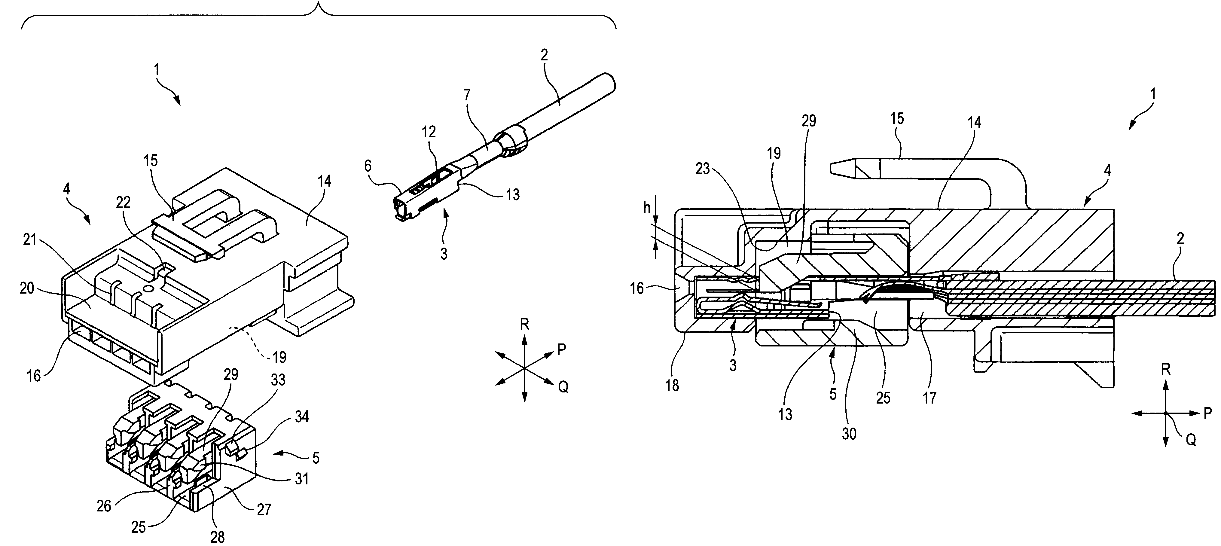
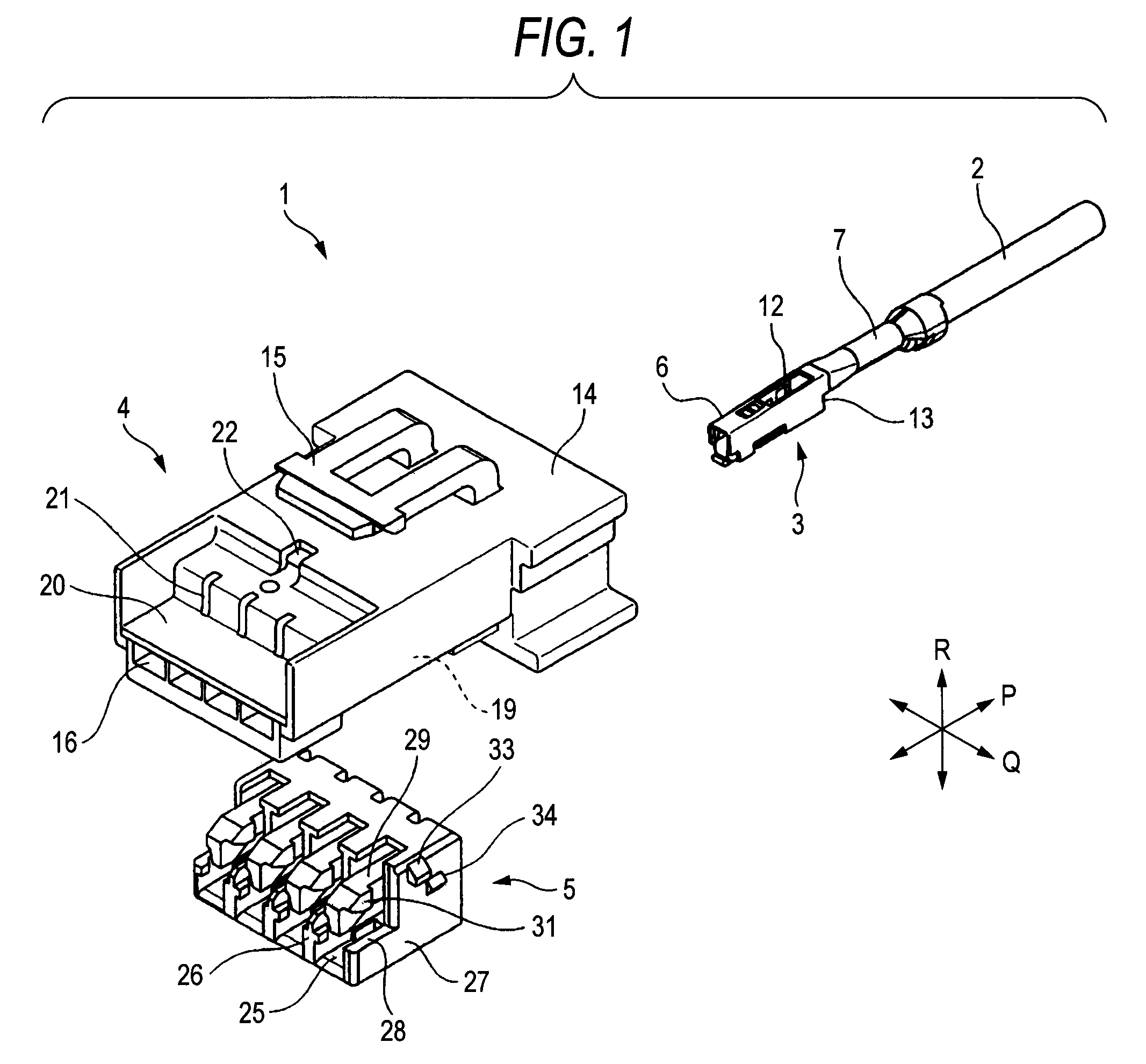
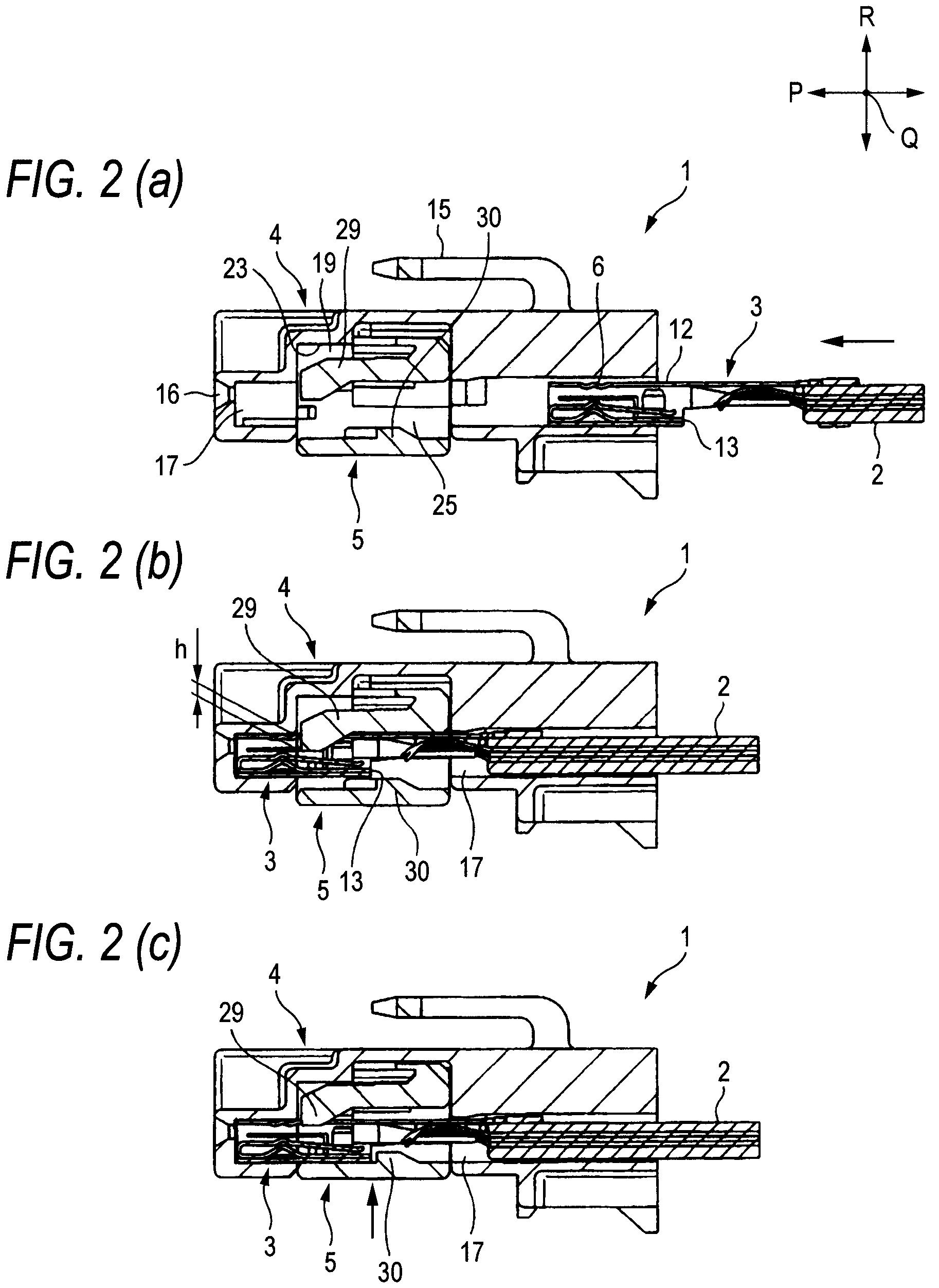
[0050]The present invention will now be described with reference to the drawings. FIG. 1 is an exploded perspective view showing one preferred embodiment of a connector of the invention. FIGS. 2A to 2C are views explanatory of double retaining of the connector, and FIG. 2A is a cross-sectional view showing a condition before a metal terminal is retained by a terminal primarily-retaining arm in a provisionally-retained condition of a terminal retaining member, and FIG. 2B is a cross-sectional view showing a condition in which the metal terminal is retained by the terminal primarily-retaining arm, and FIG. 2C is a cross-sectional view showing a condition in which the terminal retaining member is shifted to a completely-retained condition, and the metal terminal is retained by the terminal primarily-retaining arm and a terminal secondarily-retaining projection.

[0051]In FIGS. 1 and 2, a forward-rearward direction is indicated by arrow P, a left-right direction is indicated by arrow Q, a...


PUM


Abstract

When each metal terminal 3 is completely inserted into a housing 4, the metal terminal 3 is prevented from movement in forward, upward, downward, left and right directions. The metal terminal 3 is also primarily retained by a terminal retaining member 5, and is prevented from movement in a rearward direction. Then, when the terminal retaining member 5 is pushed up, and is shifted from a provisionally-retained condition to a completely-retained condition, only the terminal retaining member 5 is moved while the metal terminals 3 remain as they are. At this time, the amount of engagement of a primarily-retained portion of the metal terminal is reduced, whereas a secondarily-retaining portion of the terminal retaining member 5 is engaged with the metal terminal 3 in accordance with an upward movement of the terminal retaining member 3, thereby securing a necessary and sufficient retaining force.

Description

BACKGROUND OF THE INVENTION[0001]1. Field of the Invention[0002]This invention relates to a connector in which metal terminals are retained in a double manner, and more particularly to a connector comprising female metal terminals, a housing having terminal receiving holes and a terminal retaining member-receiving portion, and a terminal retaining member adapted to be provisionally and completely retained in the terminal retaining member-receiving portion.[0003]2. Description of the Related Art[0004]A connector has been used for connecting wire harnesses together or for connecting a wire harness to an electrical equipment. The connector includes a housing made of a synthetic resin, and metal terminals (connection terminals) each connected to an end portion of a wire can be received and held in this housing. When the connector is fitted to a mating connector, the metal terminals are electrically connected respectively to metal terminals of the mating connector.[0005]The metal termina...

Claims


Application Information

Patent Timeline
Patent Type & Authority Patents(United States)
IPC IPC(8): H01R13/514
CPCH01R13/4362
Inventor TAKAHASHI, TOSHIHARUOHTAKA, KAZUTO
Owner YAZAKI CORP
Why Eureka
Try Eureka