Surgical fastener apparatus and reinforcing material

a technology of fastener and reinforcing material, which is applied in the field of surgical and surgical stapler, can solve the problems of surgical stapler difficult to peel away, and detracting from the primary purpose of stapler, so as to facilitate the positioning of reinforcing material and facilitate gripping

Inactive Publication Date: 2009-07-14
TOWERTECH RES GROUP
View PDF5 Cites 1731 Cited by
  • Summary
  • Abstract
  • Description
  • Claims
  • Application Information

AI Technical Summary

Benefits of technology

[0016]The present invention overcomes disadvantages associated with prior art surgical staplers discussed earlier by providing a surgical stapler that has a reinforcement material holder that enables a sheet of reinforcement material to be removably held by the surgical stapler. The present invention also provides a modified sheet of reinforcement material that is removably held by the surgical stapler of the invention. The present invention also provides a method of using a reinforcement material with a surgical stapler, where the reinforcement material is removably attached to the surgical stapler without the need for adhesives, and where the reinforcement material is easily separated from the surgical stapler in use of the stapler.
[0019]The apparatus of the invention differs from prior art surgical fastener dispensers in that it is provided with a reinforcement material holder. In the preferred embodiment, the reinforcement material holder is comprised of a pair of elongate arms that are connected to the apparatus at the opposite sides of either of the fastener dispensing member and the fastener receiving member. The pair of arms extend along the lengths of the fastener dispensing member and the fastener receiving member. The arms are movable relative to both the fastener dispensing member and the fastener receiving member to facilitate the positioning of reinforcing material on the pair of arms.
[0027]Thus, the sheet of reinforcing material and the reinforcing material holder of the invention provide an economical and easily used modification of the standard surgical fastener apparatus that reinforces the line of sutures produced by the modified apparatus.

Problems solved by technology

The use of surgical staplers in securing together body tissue has been found to be disadvantaged in that the punctures formed through the body tissue as the staples are inserted can become a starting point for a tear developing in the stapled body tissue.
However, the modification of surgical staplers to include a reinforcing material adhered to the surgical stapler has detracted from the primary purpose of the stapler, i.e., to facilitate the placement of a plurality of sutures in body tissue in a quick and reliable manner.
Furthermore, the adhesive holding the material to the stapler could be difficult to peel away from the stapler, making it difficult to dispense the staples.

Method used


Image

  • Surgical fastener apparatus and reinforcing material
  • Surgical fastener apparatus and reinforcing material
  • Surgical fastener apparatus and reinforcing material

Examples


Embodiment Construction

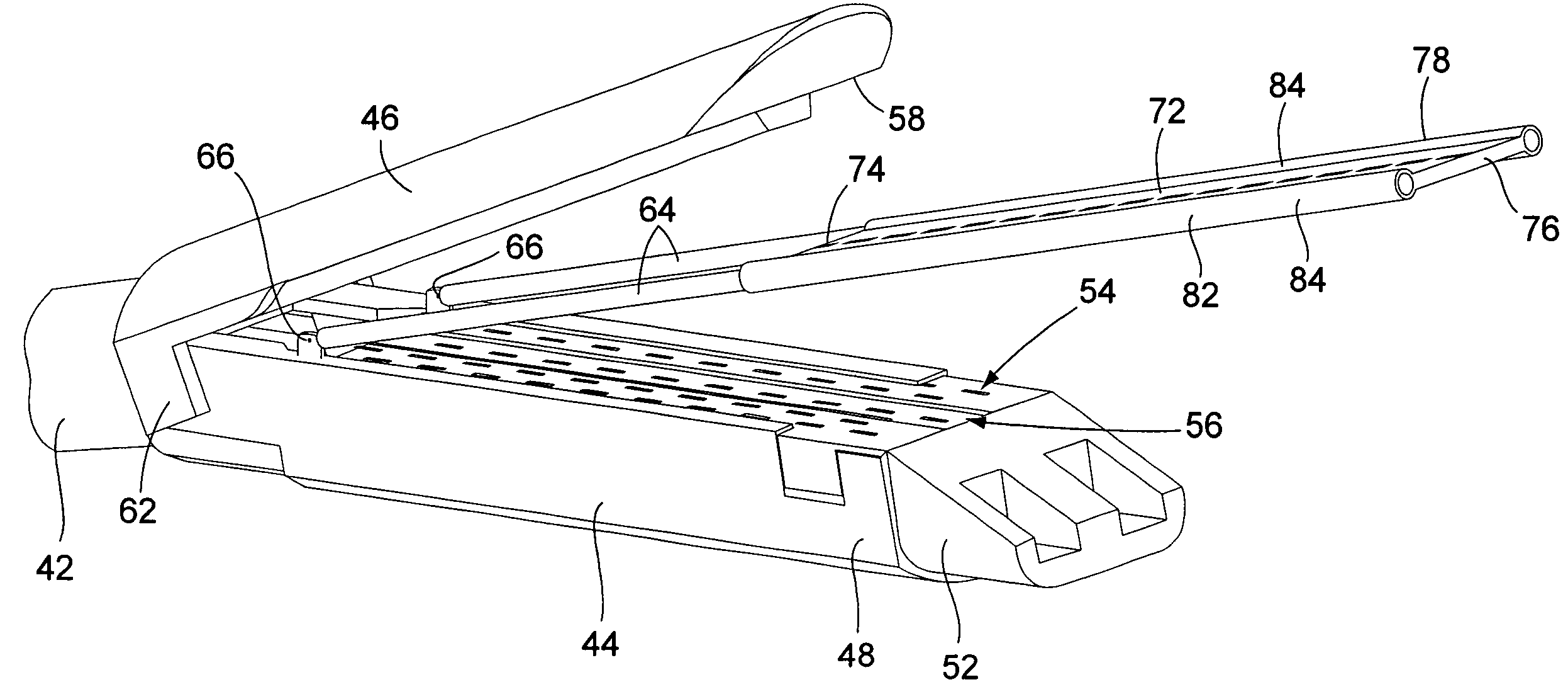
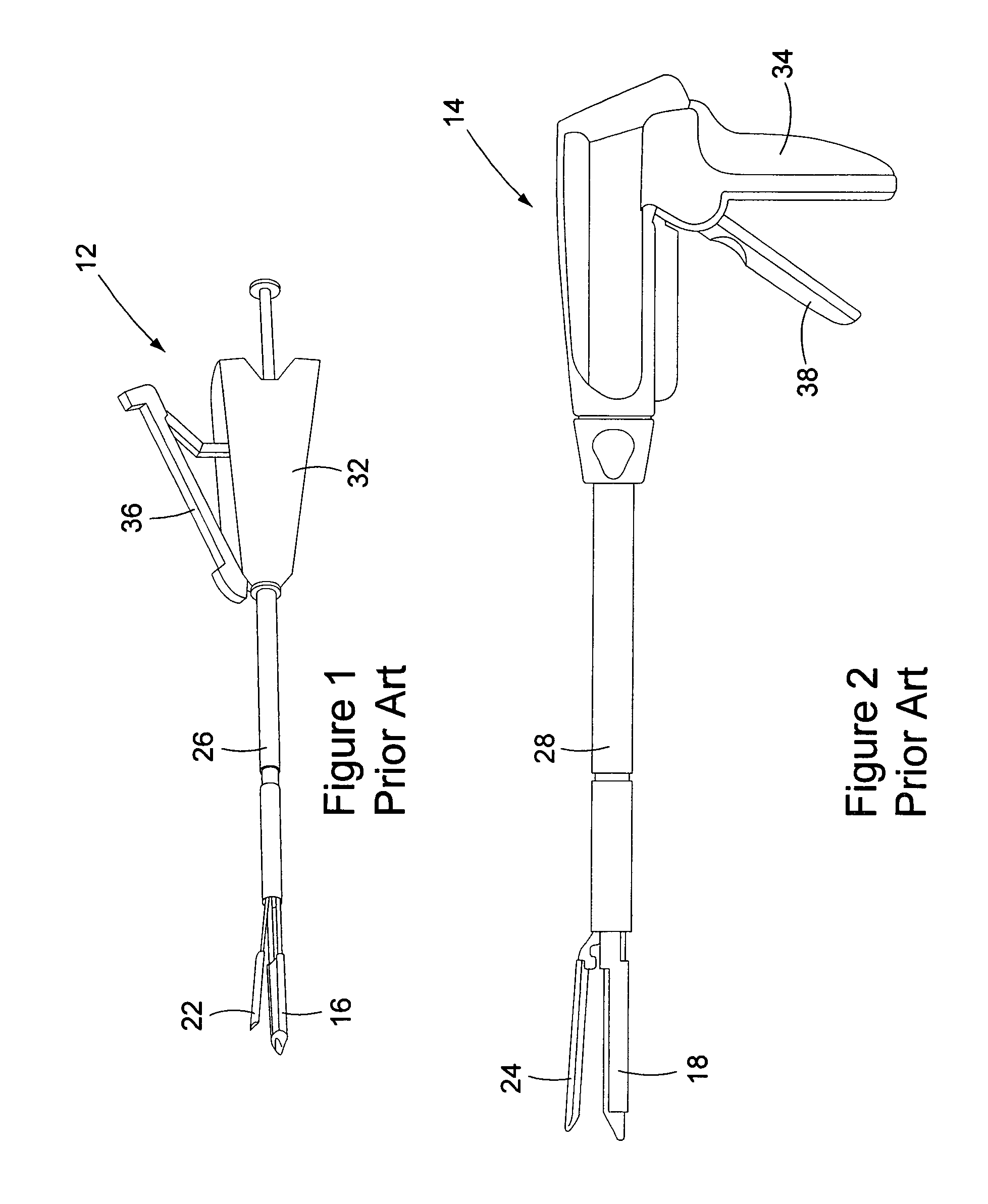
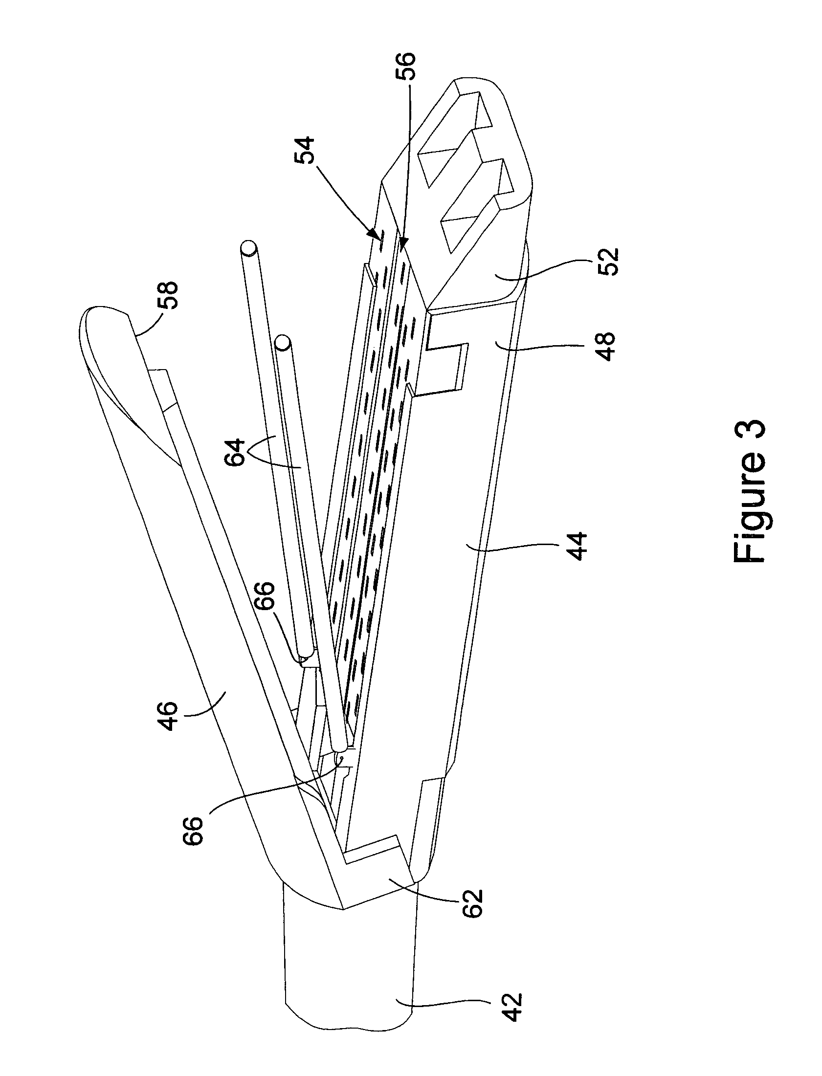
[0040]FIGS. 1 and 2 show schematic representations of two examples of prior art surgical stapler apparatus 12, 14 that can be modified with the invention. Although the apparatus examples shown in FIGS. 1 and 2 are described herein as being surgical staplers, it should be understood that the invention may be employed in modifying other types of apparatus that dispense surgical fasteners in suturing body tissue. The following description is not intended to limit the use of the invention with surgical fastener apparatus that only dispense staples.

[0041]The examples of the surgical stapler apparatus 12, 14 shown inFIGS. 1 and 2, are well known in the art. Therefore, the apparatus are described only generally herein. Each apparatus has the basic construction of a staple dispensing member 16, 18 and a staple receiving member 22, 24 mounted on a rod portion 26, 28 of the apparatus. The rod portion 26, 28 extends from a handle 32, 24 of the apparatus. Each handle 32, 34 is provided with a t...


PUM

PropertyMeasurementUnit
contact areasaaaaaaaaaa
lengthaaaaaaaaaa
widthaaaaaaaaaa

Abstract

A surgical fastener apparatus is provided with a reinforcement material holder, where the holder positions a sheet of reinforcement material adjacent body tissue that is sutured by a plurality of surgical staples dispensed by the apparatus.

Description

BACKGROUND OF THE INVENTION[0001](1) Field of the Invention[0002]The present invention pertains to a surgical fastener apparatus that dispenses a fastener reinforcing material, and the method of using the apparatus. In particular, the present invention pertains to a surgical stapler having a reinforcement material holder, where the holder positions a sheet of reinforcement material adjacent body tissue that is sutured by a plurality of surgical staples dispensed by the apparatus.[0003](2) Description of the Related Art[0004]A variety of different types of surgical staplers have been developed to assist surgeons by reducing the time required for placing a line of sutures in body tissue. Surgical staplers have been designed for use in open incision surgery, as well as in laparoscopic surgery. Examples of these staplers are shown in the Williamson, et al. U.S. Pat. No. 5,415,334, and the Francis U.S. Pat. No. 5,752,965, et al. both of which are incorporated herein by reference.[0005]Su...

Claims


Application Information

Patent Timeline
Patent Type & Authority Patents(United States)
IPC IPC(8): A61B17/10A61B17/04
CPCA61B17/07207A61B17/07292A61B17/0485A61B2017/347A61B2017/07214
Inventor DE LA TORRE, ROGER A.LACONTE, MATTHEW P.
Owner TOWERTECH RES GROUP
Why Eureka
Try Eureka