Electrical lead for an electronic device such as an implantable device

a technology of electrical leads and electronic devices, applied in the direction of coupling device connections, applications, therapy, etc., can solve the problems of mri posing a threat to patients with implantable devices, patients with metallic implants not being allowed to undergo mri scans, and heating under certain mri scanning conditions

Active Publication Date: 2009-07-14
SURGIVISION +1
View PDF17 Cites 99 Cited by
  • Summary
  • Abstract
  • Description
  • Claims
  • Application Information

AI Technical Summary

Problems solved by technology

MRI may, however, pose a threat to patients that have implantable devices, such as, without limitation, a deep brain stimulation (DBS) device, a pacemaker, a neurostimulator, or a cardio defibrillator.
Currently, patients with metallic implants are not allowed to undergo an MRI scan.
One of the main reasons for this is the excessive heating caused by the electromagnetic field concentration around the leads of an implant during an MRI procedure.
These results indicate that heating may be hazardous under certain MRI scanning conditions.
However, many modem MRI pulse sequences, such as fast spin-echo or steady-state free precession (SSFP), require high RF power levels and therefore there is no guarantee that good quality images can be acquired if RF power is limited.
However in this design, high permittivity materials must be employed.
This requirement may create flexibility problems since high permittivity materials are brittle and rigid.
In such a case, miniaturization of the design is a difficult task.
Both of the designs ensure electromagnetic interference is not a problem, however safety in terms of heating is not guaranteed.
High current may still be flowing through long cables and these high currents may cause excessive heating and buns.
However, the electrical to optical and optical to electrical energy conversion efficiency is limited and therefore the lifetime of the pulse generator is reduced significantly.
Miniaturization in this case is also a difficult task.

Method used


Image

  • Electrical lead for an electronic device such as an implantable device
  • Electrical lead for an electronic device such as an implantable device
  • Electrical lead for an electronic device such as an implantable device

Examples


Embodiment Construction

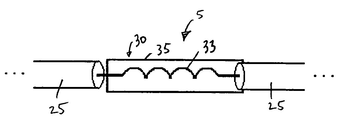
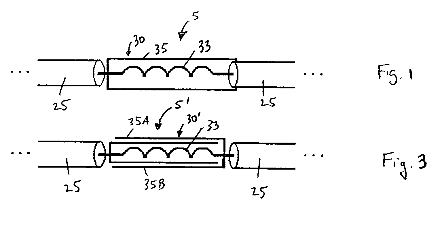
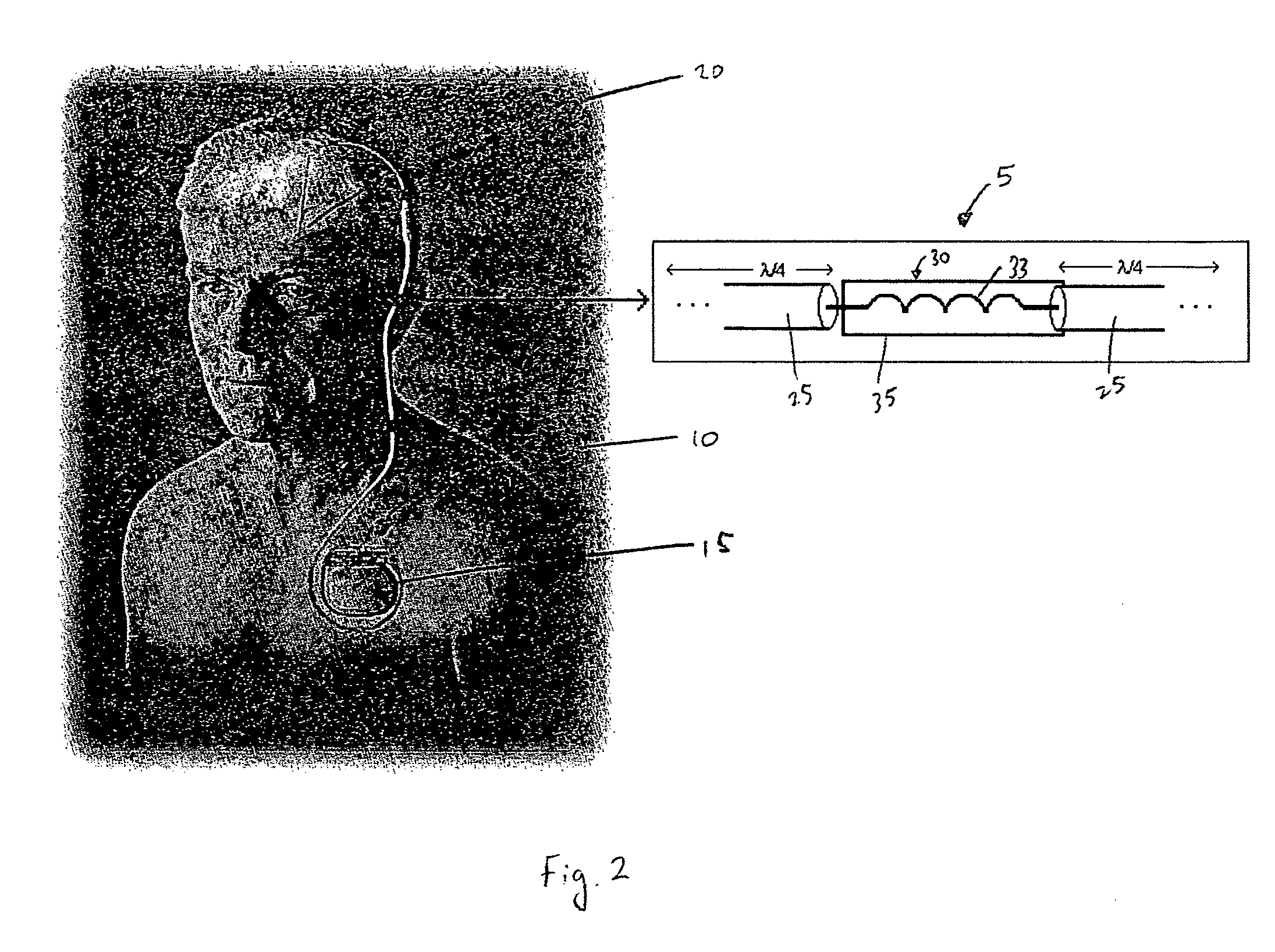
[0029]FIG. 1 is a schematic diagram of an electrical lead 5 for an electronic device carried by the body of a patient according to a first embodiment of the present invention. As used herein, the term “patient”shall refer to any member of the animal kingdom, including human beings. As used herein, the terms “carried by the body of the patient” in reference to as device shall mean that the device may be implanted within the patient body, worn on or attached externally to the patient's body, or some combination thereof. In the preferred embodiment as shown schematically in FIG. 2, the electrical lead 5 shown in FIG. 1 forms a part of an implantable device 10, such as, without limitation, a deep brain stimulation (DBS) device, a pacemaker, a neurostimulator, or a cardio defibrillator, to deliver electrical signals (e.g., electrical pulses) from a generator 15 to a location 20, such as an organ or some other tissue, within the body to which the electrical signals are to be applied (for ...


PUM


Abstract

A lead for an electronic device which resists the induction of a current from an electromagnetic field external to said lead includes one or more pairs of adjacent segments of electrical wire, each of the pairs including a first segment of electrical wire and a second segment of electrical wire. The lead also includes one or more shielded RF chokes, wherein each of the shielded RF chokes is provided between the first segment of electrical wire and the second segment of electrical wire of a respective one of the one or more pairs of adjacent segments. Also, an implantable device that includes a generator for generating one or more electrical pulse and a lead as described for delivering the pulses to tissue within a patient's body. A method for making the described implantable device is also provided.

Description

CROSS-REFERENCE TO RELATED APPLICATION[0001]This application claims the benefit of U.S. Provisional Application No. 60 / 677,418, entitled “MRI Compatible Implantable Devices,” which was filed on May 4, 2005, the disclosure of which is incorporated herein by reference.FIELD OF THE INVENTION[0002]The present invention relates to electrical leads for devices such as, without limitation, implantable devices, and in particular to an electrical lead which resists the induction of currents from an external electromagnetic field and therefore reduces the likelihood of excessive heating from such fields.BACKGROUND OF THE INVENTION[0003]Magnetic resonance imaging (MRI) is generally regarded as an extremely safe, non invasive diagnostic technique. MRI may, however, pose a threat to patients that have implantable devices, such as, without limitation, a deep brain stimulation (DBS) device, a pacemaker, a neurostimulator, or a cardio defibrillator. Currently, patients with metallic implants are no...

Claims


Application Information

Patent Timeline
Patent Type & Authority Patents(United States)
IPC IPC(8): A61B5/04
CPCA61N1/05A61N1/08H01R13/5224H01R13/6633A61N1/3718A61N2001/086A61N1/086
Inventor ATALAR, ERGINFERHANOGLU, ONUR
Owner SURGIVISION
Why Eureka
Try Eureka