Architectural panel fabrication system

Active Publication Date: 2009-07-21
WMH CONSULTING
View PDF62 Cites 98 Cited by
  • Summary
  • Abstract
  • Description
  • Claims
  • Application Information

AI Technical Summary

Benefits of technology

[0007]The present invention relates to an extruded assembly system for mounting a structure to a member surface. The attachment system includes an anchor attached to the surface. The anchor has a pair of sidewalls extending substantially perpendicular therefrom. The pair of sidewalls form an anchor channel and have one or more first flanges formed on at least one of the sidewalls facing the anchor channel. The attachment system also includes a panel frame having a body. The body has at least one lateral surface extending substantially perpendicularly and the body is inserted into the anchor channel. The body has first and second sidewalls ext

Problems solved by technology

However, the assembly systems currently in use are expensive and require considerable time and labor to install and fabricate.
Systems utilizing screws and other fasteners add labor costs because of additional time required for installation and fabrication.
The leveling and the alignment process further lengthens the period of time required for proper installation.
Furthermore, if the panel needs to be removed due to damage, most assembly systems require the removal of numerous panels to replace the damaged one.
This results in increased maintenance costs for maintaining the assembly system.
The condensation drainage often leads to future leakage and other water damage.
Systems that use caulk as a sealant potentially leads to caulk migrating past the face of the panel.
The caulk also absorbs contaminants as it ages and causes discoloration and breaking down of the caulk, thereby eliminating the aesthetic benefits of the assembly system.
Dry set systems often fail due to improper panel alignment which leads to future leakage within the framing system.
Furthermore, curren

Method used


Image

  • Architectural panel fabrication system
  • Architectural panel fabrication system
  • Architectural panel fabrication system

Examples


Embodiment Construction

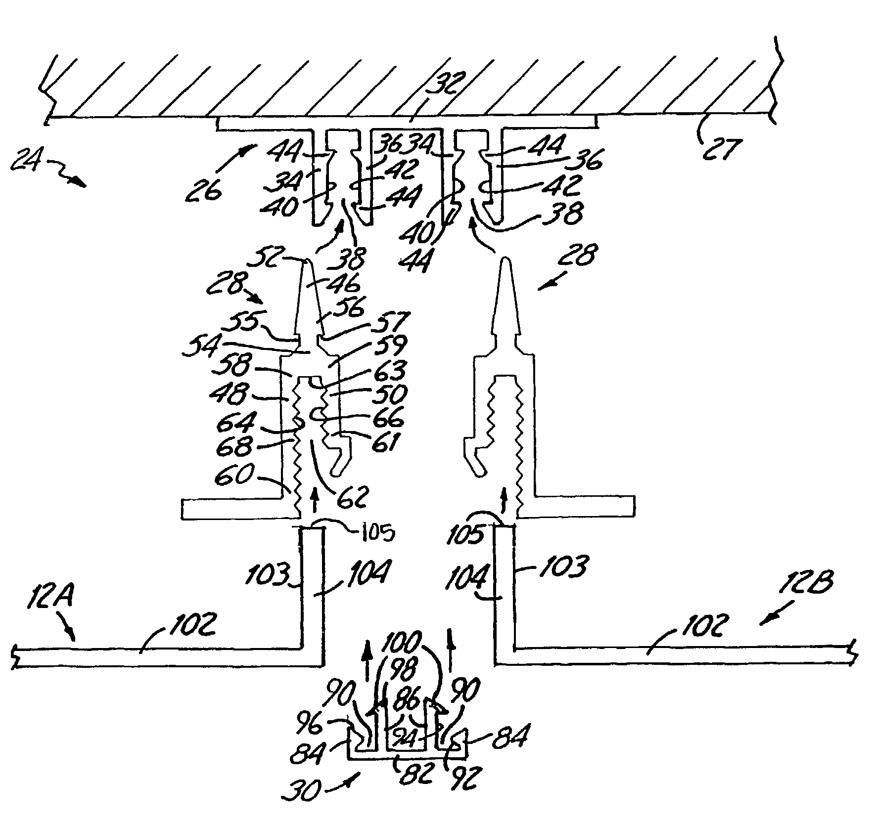
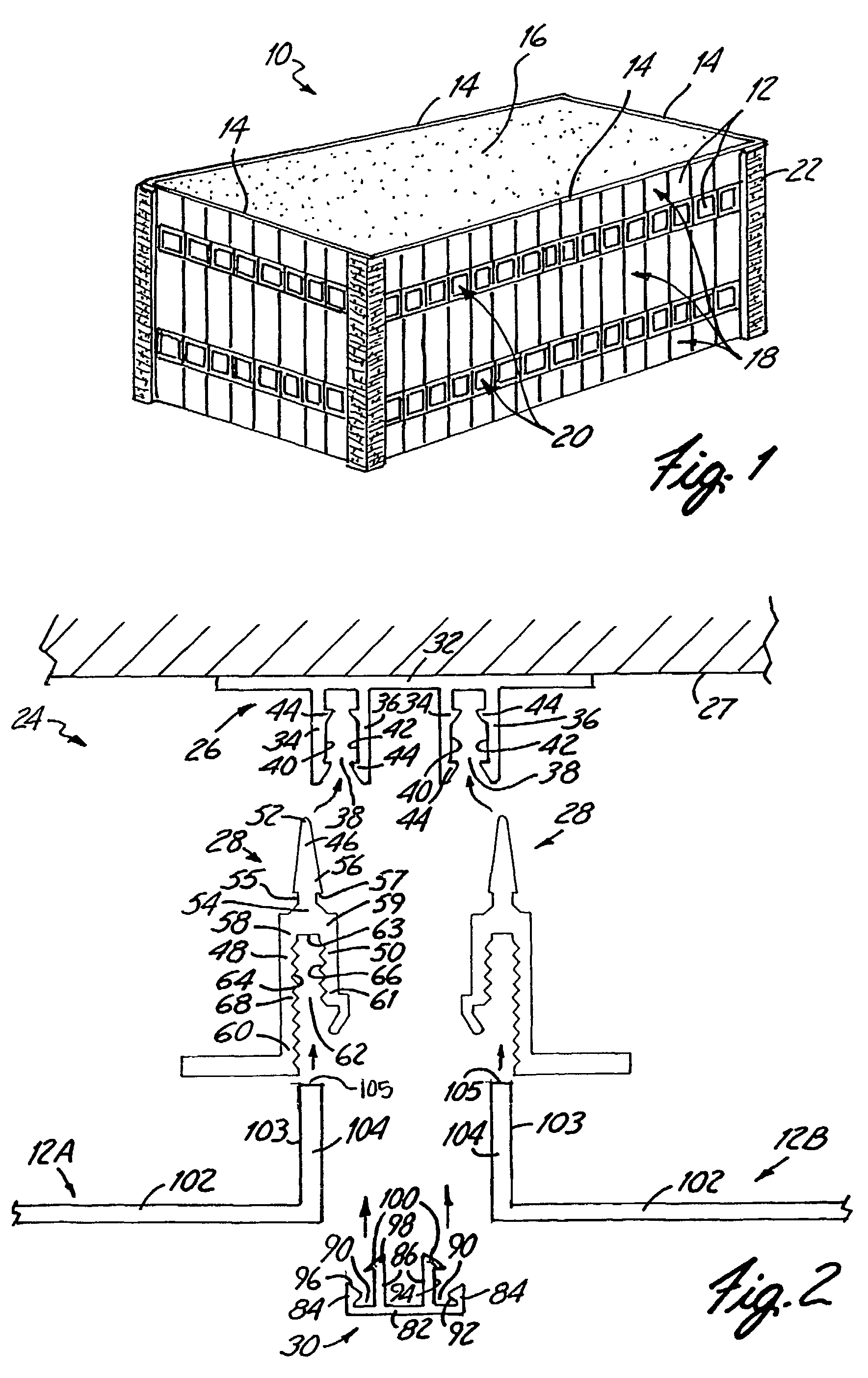
[0020]FIG. 1 is a perspective view of a building 10 using an inventive assembly system (not shown) to attach structural members 12 to the building 10. The building 10 has at least four support walls 14 and a roof 16. The structural members 12 are attached to the support walls 14 of the building 10. In FIG. 1, the structural members 12 may include composite panels 18, glass windows 20 or other ornamental or functional building components. Also, brick 22 is mounted to the building 10 at the corners. The building 10 is used as an example of a building utilizing the inventive assembly system. Those skilled in the art will recognize that the present invention may be employed on buildings of varying size and shape, as well as in connection with different types of structural members, including composite, aluminum, glass, stone, and precast. The structural members may be attached to other surfaces on the building 10, including the support structure, building support, or a generally vertical...


PUM


Abstract

An fabrication system used for mounting a structural member to a surface including an anchor attached to the surface. The anchor has a pair of sidewalls extending substantially perpendicular therefrom and forming an anchor channel with one or more first flanges formed on at least one of the sidewalls facing the anchor channel. The fabrication system also includes a panel frame having a body for insertion into the anchor channel. The body has at least one lateral surface extending substantially perpendicularly therefrom. First and second sidewalls extend from the body to define a frame channel for receiving an edge portion of the structural member. At least one of the first and second sidewalls has a serrated inner face facing the frame channel.

Description

BACKGROUND OF THE INVENTION[0001]The present invention relates to a panel assembly system for attaching architectural wall panels to a building. In particular, the present invention relates to a snap-fit assembly that assures proper alignment of the panels, ease of installation and lower fabrication and installation costs.[0002]For certain types of buildings, panels are often used to cover the exterior walls of the building. The panels are used for aesthetic purposes and can be economically beneficial to the owner. Typically a single panel can be used to cover a large section of the building. Assembly or (framing) systems are commonly used to attach panels (such as composite, aluminum, glass, stone, precast, etc.) to an exterior surface or a support structure of a building. However, the assembly systems currently in use are expensive and require considerable time and labor to install and fabricate.[0003]Generally most assembly systems for attaching panels to a building support utili...

Claims


Application Information

Patent Timeline
IPC IPC(8): E04B2/90E04B2/96E04F13/08
CPCE04F13/0889E04F13/0805E04F13/0803
Inventor HERBST, WALTER M.HERBST, MICHAEL P.
Owner WMH CONSULTING
Why Eureka
Try Eureka