Heat exchanger with perforated plate in header

a heat exchanger and perforated plate technology, applied in indirect heat exchangers, lighting and heating apparatus, refrigeration components, etc., can solve the problems of significant reduction of heat exchanger efficiency, adversely affecting heat exchanger efficiency, and two-phase maldistribution, so as to reduce maldistribution

Inactive Publication Date: 2009-07-21
CARRIER CORP
View PDF46 Cites 25 Cited by
  • Summary
  • Abstract
  • Description
  • Claims
  • Application Information

AI Technical Summary

Benefits of technology

[0012]It is a general object of the invention to reduce maldistribution of refrigerant flow in a refrigerant vapor compression system heat exchanger having a plurality of multi-channel tubes extending between a first header and a second header.

Problems solved by technology

Non-uniform distribution, also referred to as misdistribution, of two-phase refrigerant flow is a common problem in parallel tube heat exchangers which adversely impacts heat exchanger efficiency.
Among other factors, two-phase maldistribution problems are caused by the difference in density of the vapor phase refrigerant and the liquid phase refrigerant present in the inlet header due to the expansion of the refrigerant as it traversed the upstream expansion device.
Obtaining uniform refrigerant flow distribution amongst the relatively large number of small cross-sectional flow area refrigerant flow paths is even more difficult than it is in conventional round tube heat exchangers and can significantly reduce heat exchanger efficiency.

Method used


Image

  • Heat exchanger with perforated plate in header
  • Heat exchanger with perforated plate in header
  • Heat exchanger with perforated plate in header

Examples


Embodiment Construction

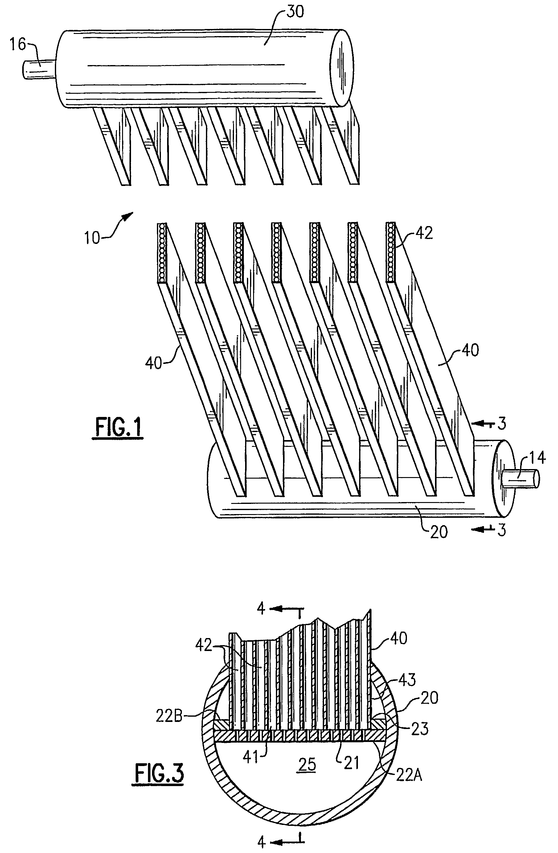
[0035]The heat exchanger 10 of the invention will be described in general herein with reference to the illustrative single pass, parallel-tube embodiment of a multi-channel tube heat exchanger as depicted in FIG. 1. The heat exchanger 10 includes an inlet header 20, an outlet header 30, and a plurality of longitudinally extending multi-channel heat exchanger tubes 40. In the illustrative embodiment of the heat exchanger 10 depicted therein, the heat exchange tubes 40 are shown arranged in parallel relationship extending generally vertically between a generally horizontally extending inlet header 20 and a generally horizontally extending outlet header 30. The inlet header 20 defines an interior volume for receiving a fluid from line 14 to be distributed amongst the heat exchange tubes 40. The outlet header 30 defines an interior volume for collecting fluid from the heat exchange tubes 40 and directing the collected fluid therefrom through line 16.

[0036]The plurality of longitudinally...


PUM


Abstract

A heat exchanger includes an inlet header, an outlet header and a plurality of flat, multi-channel heat exchange tubes extending therebetween. A longitudinally extending member divides the interior of the header into a first chamber on one side thereof for receiving a fluid and a second chamber on the other side thereof. A plurality of multi-channel heat exchange tubes extend between the headers with the respective inlet end of each heat exchange tube passing into the second chamber of the inlet header. Fluid passes through a series of longitudinally spaced openings in the longitudinally extending member for distribution to the inlets to the channels of the multi-channel heat exchange tubes. The fluid may undergo expansion as it passes through the openings.

Description

CROSS-REFERENCE TO RELATED APPLICATION[0001]Reference is made to and this application claims priority from and the benefit of U.S. Provisional Application Ser. No. 60 / 649,434, filed Feb. 2, 2005, and entitled MINI-CHANNEL HEAT EXCHANGER WITH FLUID EXPANSION USING RESTRICTIONS IN THE FORM OF INSERTS IN THE PORTS, which application is incorporated herein in its entirety by reference.FIELD OF THE INVENTION[0002]This invention relates generally to refrigerant vapor compression system heat exchangers having a plurality of parallel tubes extending between a first header and a second header and, more particularly, to providing expansion of refrigerant within the inlet header for improving distribution of two-phase refrigerant flow through the parallel tubes of the heat exchanger.BACKGROUND OF THE INVENTION[0003]Refrigerant vapor compression systems are well known in the art. Air conditioners and heat pumps employing refrigerant vapor compression cycles are commonly used for cooling or cool...

Claims


Application Information

Patent Timeline
Patent Type & Authority Patents(United States)
IPC IPC(8): F28F9/22
CPCF25B39/028F25B41/06F28F9/0278F28D1/05383F28F9/0214F28F9/0224F25B39/00F25B2341/0661F25B41/385F25B41/39F28F9/04F28F9/22
Inventor GORBOUNOV, MIKHAIL B.VAISMAN, IGOR B.VERMA, PARMESHFARZAD, MOSHENDANIELS, MARK A.WYSOCKI, JOSEPH B.
Owner CARRIER CORP
Why Eureka
Try Eureka