Tubular spring for actuator, and method for assembling the tubular spring

a technology of tubular springs and actuators, which is applied in the direction of machines/engines, generators/motors, device details, etc., can solve the problems of even more damage to actuators, and achieve the effect of not affecting the spring characteristics of tubular springs and uniform loading

Inactive Publication Date: 2009-07-21
ROBERT BOSCH GMBH
View PDF21 Cites 13 Cited by
  • Summary
  • Abstract
  • Description
  • Claims
  • Application Information

AI Technical Summary

Benefits of technology

[0007]The tubular spring according to the present invention for an actuator, and the method according to the present invention for assembly, have the advantage that assembly engagements in the tubular spring make possible uniform preloading of the tubular spring and of the actuator, and stress-free welding of the tubular spring to the actuator head and actuator foot.
[0008]Advantageously, the assembly engagements are disposed in at least one of the otherwise continuous end regions of the tubular spring. The result, on the one hand, is that the spring characteristics of the tubular spring are not negatively influenced. A positive influence, with a longer possible actuator stroke, is possible as a result of introduction of the assembly engagements in only one end region.
[0009]It is additionally advantageous that the assembly engagements are disposed on the tubular spring symmetrically and in paired fashion, or equidistantly at identical angular spacings, so that uniform loading is possible.
[0010]It is furthermore advantageous that a preassembly of the actuator module in the load-free state is first performed before the actuator module is inserted into an assembly apparatus for preloading and final assembly. As a result, the actuator is already protected from damage due to shear forces, and can be stored and transported until further processed.

Problems solved by technology

This configuration is disadvantageous in particular because of the need to configure the stacked actuator in hollow fashion so that the tie rod can be accommodated in the recess.
This makes the actuator even more susceptible to damage during preassembly and assembly.
The particular disadvantage of this actuator is that the preload of the actuator is defined solely by the elasticity of the spring sleeve.

Method used


Image

  • Tubular spring for actuator, and method for assembling the tubular spring
  • Tubular spring for actuator, and method for assembling the tubular spring
  • Tubular spring for actuator, and method for assembling the tubular spring

Examples


Embodiment Construction

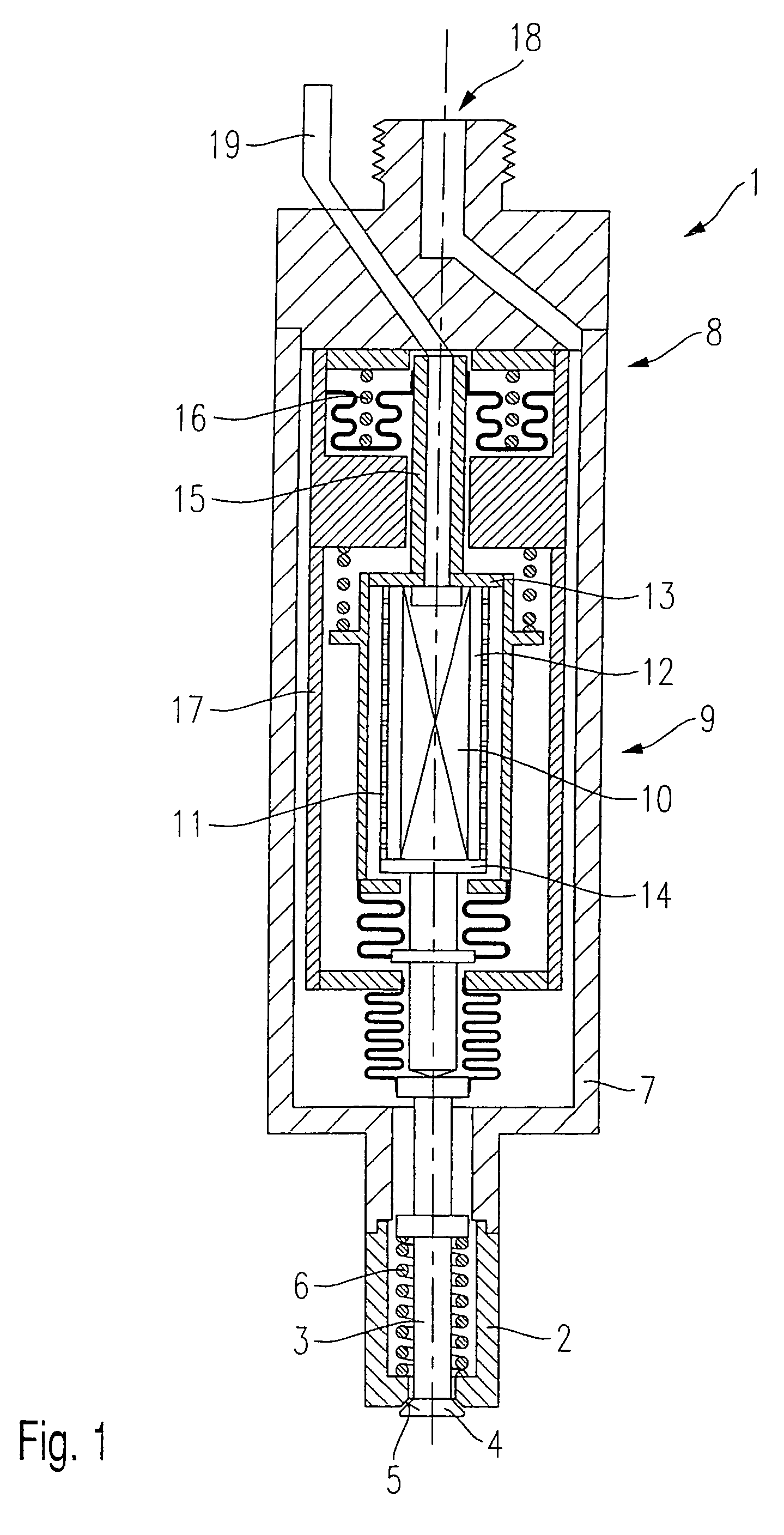
[0018]FIG. 1 shows, in a highly schematic depiction, a fuel injection valve suitable for being fitted with a tubular spring configured according to the present invention.

[0019]Fuel injection valve 1 depicted in FIG. 1 is suitable, in particular, as a fuel injection valve 1 for direct injection of fuel into a combustion chamber (not depicted further) of an internal combustion engine.

[0020]Fuel injection valve 1 encompasses a nozzle body 2 in which a valve needle 3 is guided. The latter has at one outflow end a valve closure element 4 that forms a sealing fit with a valve seat surface 5. Fuel injection valve 1 is embodied as an outward-opening fuel injection valve 1. A return spring 6, disposed in nozzle body 2, impinges upon valve needle 3 in such a way that fuel injection valve 1 is held closed in the idle phase, and valve needle 3 is returned back to its idle position after the opening phase.

[0021]Nozzle body 2 opens into a housing 7 in which a hydraulic coupler 8 and an actuator m...


PUM


Abstract

A tubular spring is provided for preloading a piezoelectric or magnetostrictive actuator for the actuation of fuel injection valves for fuel injection systems of internal combustion engines. The tubular spring has at least two assembly engagements for uniform preloading of the tubular spring.

Description

FIELD OF THE INVENTION[0001]The present invention relates to a tubular spring for an actuator and a method for assembling the tubular spring.BACKGROUND INFORMATION[0002]Piezoelectric or magnetostrictive actuators for the actuation of fuel injection valves for fuel injection systems of internal combustion engines are usually preloaded by way of a spring in order to eliminate tensile and shear forces. The residual load of the fuel injection valve's return spring, present even when the fuel injection valve is closed, is usually used to generate the preload.[0003]An actuator, e.g., for the actuation of fuel injection valves for fuel injection systems of internal combustion engines, that has multiple layers made of a piezoelectric or magnetostrictive material arranged in stacked fashion, is described in published German patent document DE 199 51 012. The actuator is preloaded by way of a tie rod disposed in a central recess, by an opposite-direction thread. Immobilization and energy tran...

Claims


Application Information

Patent Timeline
Patent Type & Authority Patents(United States)
IPC IPC(8): H01L41/02H01L41/12F02M51/06F02M63/00F16F1/02H01L41/053H01L41/25H02N2/04
CPCF02M51/0603H01L41/0536F16F1/028F02M2200/26H01L41/25H10N30/886H10N30/03
Inventor STIER, HUBERTSCHMIEDER, DIETMARDEPONTE, RENE
Owner ROBERT BOSCH GMBH
Why Eureka
Try Eureka