Flashlight housing

a technology of led flashlights and housings, which is applied in the direction of transportation and packaging, semiconductor devices for light sources, lighting and heating apparatus, etc., can solve the problems of high power consumption requirements, manufacturing difficulties, and damage to the emitter chips and circuitry required to drive the led, so as to improve the overall heat management of the overall flashlight assembly, improve air circulation and heat dissipation, and improve the effect of heat managemen

Inactive Publication Date: 2005-02-03
EMISSIVE ENERGY A DELAWARE
View PDF13 Cites 130 Cited by
  • Summary
  • Abstract
  • Description
  • Claims
  • Application Information

AI Technical Summary

Benefits of technology

[0009] In particular, the assembled package is then placed into a flashlight housing. The flashlight housing of the present invention is further modified in accordance with the present disclosure to further enhance the heat management of the overall flashlight assembly in that the housing has vent openings in the side wall thereof. The vent openings are provided in the side wall at locations adjacent the outer enclosure of the package. In this manner, improved air circulation and heat dissipation is provided by facilitating the circulation of free air around the heat dissipating surfaces of the outer enclosure.
[0010] Accordingly, one of the objects of the present invention is the provision of an assembly for packaging a high intensity

Problems solved by technology

These high brightness packages differ from conventional LED lamps in that they use emitter chips of much greater size, which accordingly have much higher power consumption requirements.
However, due to their unique shape, size and power consumption requirements they present manufacturing difficulties that were originally unanticipated by the LED manufacturers.
If this heat is not effectively dissipated, it may cause damage to the emitter chip and the circuitry required to drive the LED.
While these a

Method used


Image

  • Flashlight housing
  • Flashlight housing
  • Flashlight housing

Examples


Embodiment Construction

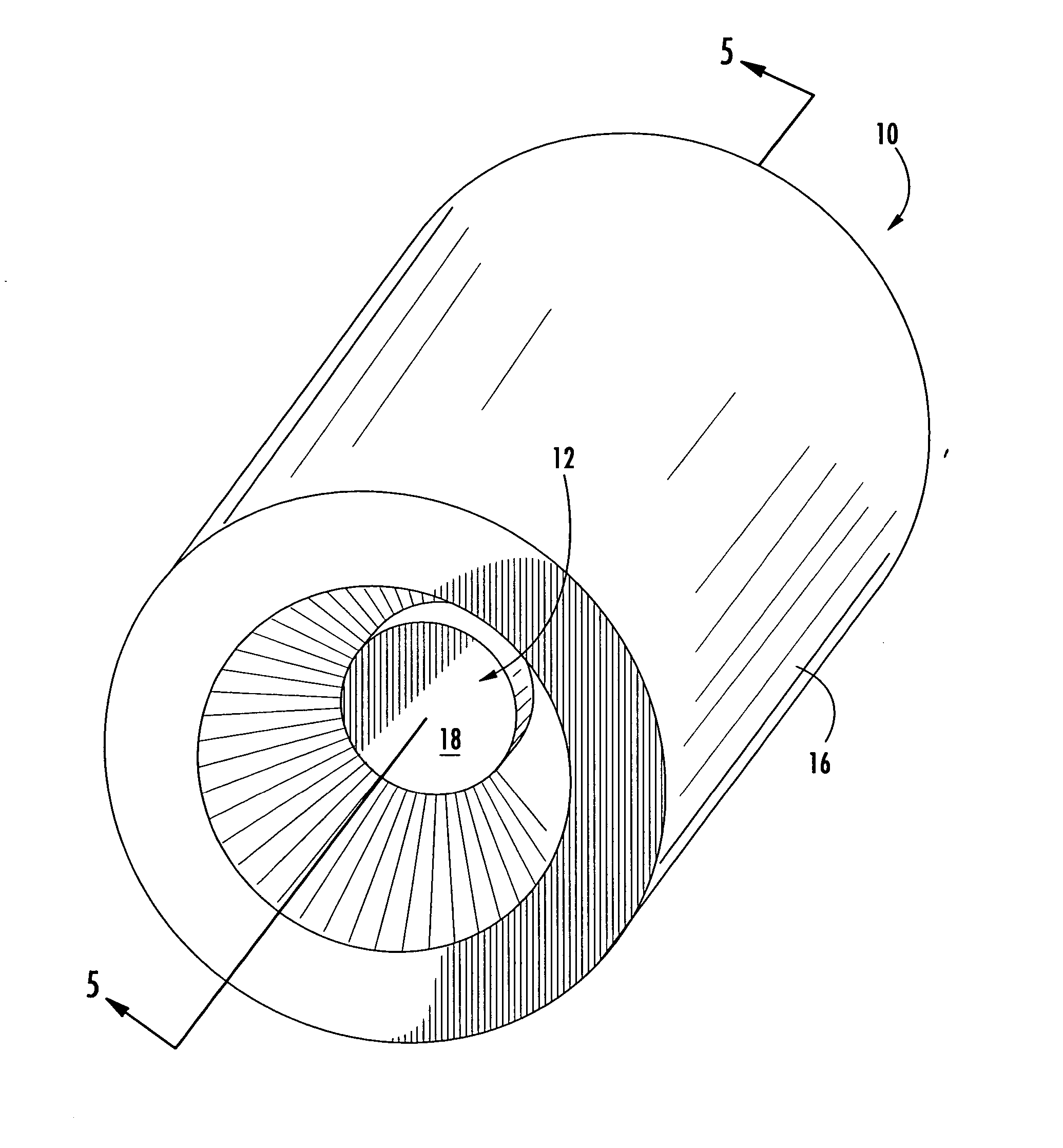
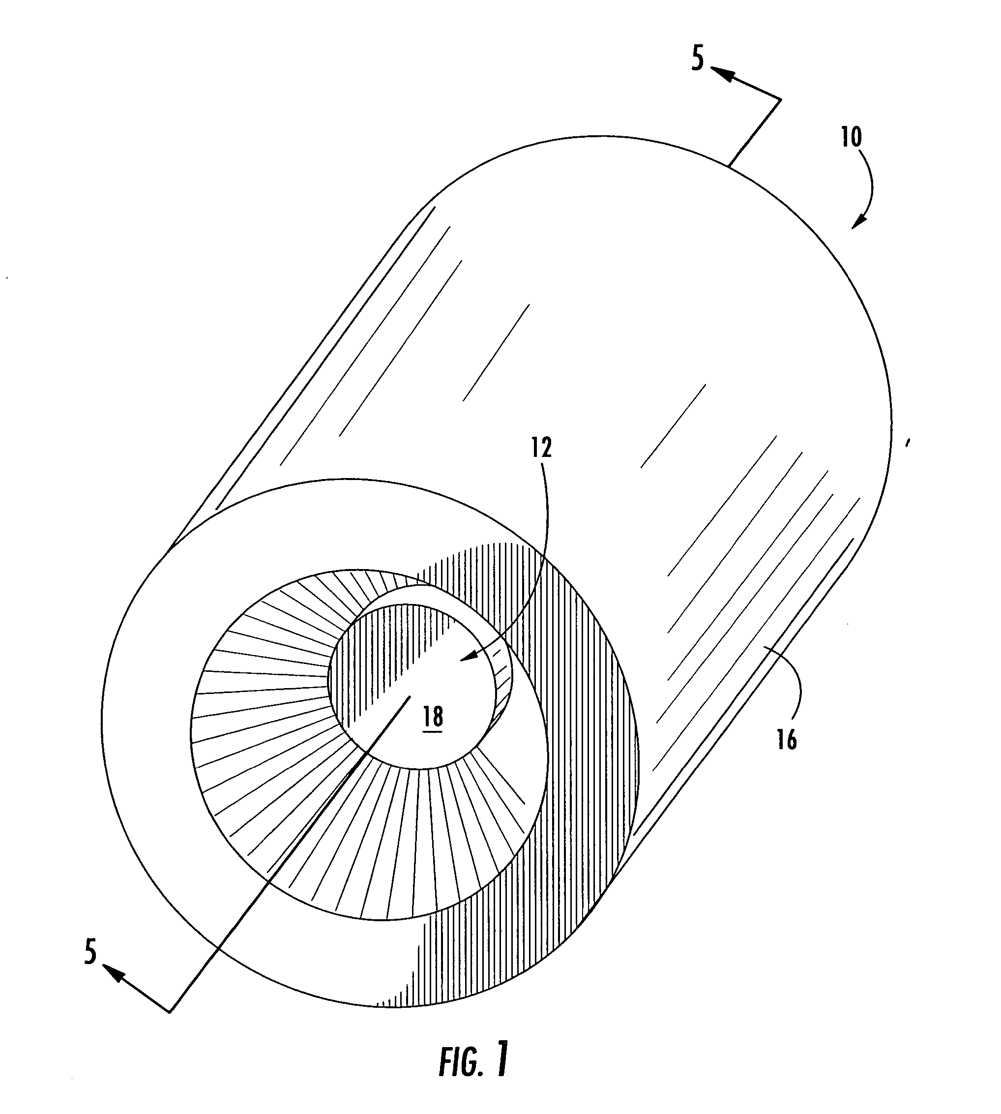
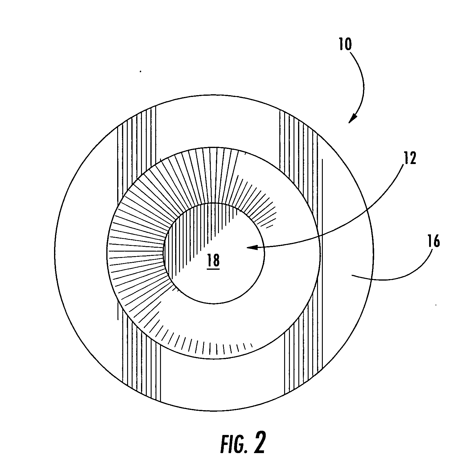
[0031] Referring now to the drawings, the light emitting diode (LED) lighting assembly of the present invention is illustrated and generally indicated at 10 in FIGS. 1-5. Further, a schematic diagram is shown in FIG. 6 generally illustrating the present invention incorporated into a flashlight circuit. As will hereinafter be more fully described, the present invention illustrates an LED lighting assembly 10 for further incorporation into a lighting device. For the purposes of providing a preferred embodiment of the present invention, the device 10 will be shown incorporated into a flashlight, however, the present invention also may be incorporated into any other lighting device such as architectural specialty lighting or vehicle lighting. In general, the present invention provides a means for packaging a high intensity LED lamp that includes integral heat sink capacity, electrical connectivity and an optical assembly for controlling the light output from the LED. The present inventi...


PUM


Abstract

The present invention provides a lighting assembly that incorporates a high intensity LED package into an integral housing for further incorporation into other useful lighting devices. The present invention primarily includes three housing components, namely an inner mounting die, an outer enclosure and an outer housing that cooperate to enhance the heat management of the overall assembly. The inner and outer components cooperate to retain the LED package, provide electrical and control connections, provide integral heat sink capacity and includes an integrated reflector cup. Surface area enhancements on the outer surface of the outer enclosure are aligned with openings in the outer housing to allow efficient air flow around the LED assembly to enhance cooling. In this manner, high intensity LED packages can be incorporated into lighting assemblies with reduced risk of overheating and malfunction.

Description

CROSS-REFERENCE TO RELATED APPLICATIONS [0001] This application is related to and claims priority from earlier filed provisional patent application No. 60 / 338,893, filed Dec. 10, 2001 and is a continuation-in-part of U.S. patent application Ser. No. 10 / 833,556, filed Apr. 28, 2004, which is a continuation-in-part of U.S. patent application Ser. No. 10 / 659,575, filed Sep. 10, 2003, which is a continuation-in-part of U.S. patent application Ser. No. 10 / 315,336, filed Dec. 10, 2002.BACKGROUND OF THE INVENTION [0002] The present invention relates to a new assembly for providing a housing for use in conjunction with a high intensity LED lighting assembly. More specifically, this invention relates to an assembly for housing a high intensity LED flashlight that includes integrally formed vent openings for enhancing the thermal performance of the entire packaged device. [0003] Currently, several manufacturers are producing high brightness light emitting diode (LED) packages in a variety of ...

Claims


Application Information

Patent Timeline
IPC IPC(8): F21L4/02F21V29/00
CPCF21L4/027F21S48/328F21V19/001F21V29/004F21V29/89Y10S362/80F21V29/767F21V29/83F21V29/87F21Y2101/02F21Y2115/10F21V29/70
Inventor GALLI, ROBERT D.
Owner EMISSIVE ENERGY A DELAWARE
Why Eureka
Try Eureka