Lighting device with an improved housing

a technology of lighting devices and housings, applied in the direction of lighting and heating apparatus, semiconductor devices for light sources, refractors, etc., to achieve the effect of improving the heat management of lighting devices

Inactive Publication Date: 2017-04-13
SIGNIFY HLDG BV
View PDF2 Cites 5 Cited by
  • Summary
  • Abstract
  • Description
  • Claims
  • Application Information

AI Technical Summary

Benefits of technology

[0027]By having the first angle to be larger than the second angle, the heat management of the lighting device may be improved in combination with the light distribution of the lighting device. The first angle may be larger than 180° while the second angle is smaller than 180°

Problems solved by technology

In addition, at least one side of the collar portion is not enclosed so air may circulate freely and dissipate the heat generated from the lighting devices.

Method used


Image

  • Lighting device with an improved housing
  • Lighting device with an improved housing
  • Lighting device with an improved housing

Examples


Embodiment Construction

[0036]The present invention will now be described more fully hereinafter with reference to the accompanying drawings, in which currently preferred embodiments of the invention are shown. This invention may, however, be embodied in many different forms and should not be construed as limited to the embodiments set forth herein; rather, these embodiments are provided for thoroughness and completeness, and fully convey the scope of the invention to the skilled person.

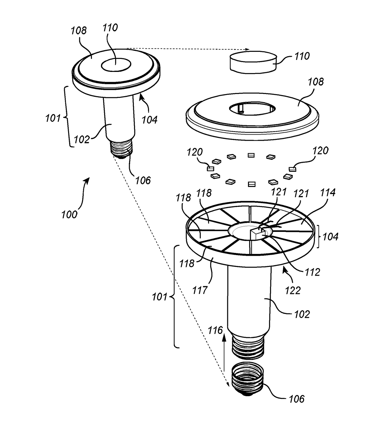
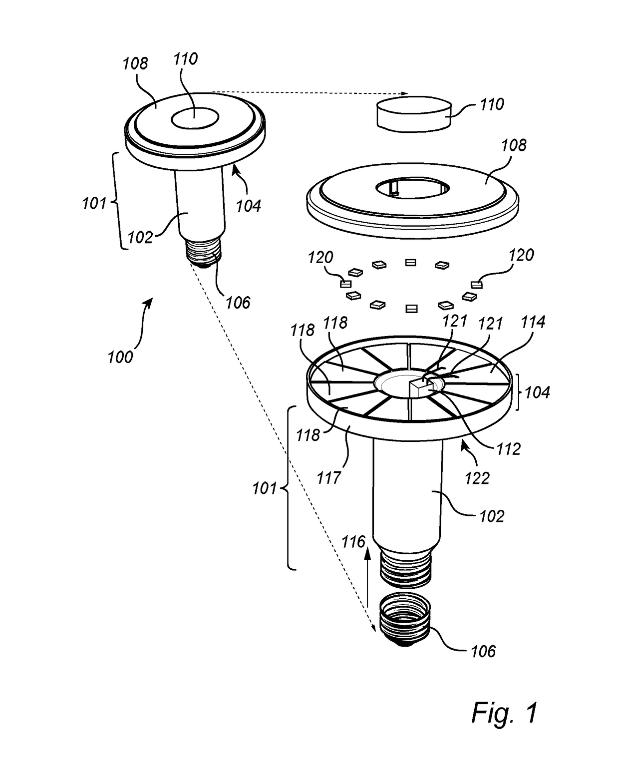
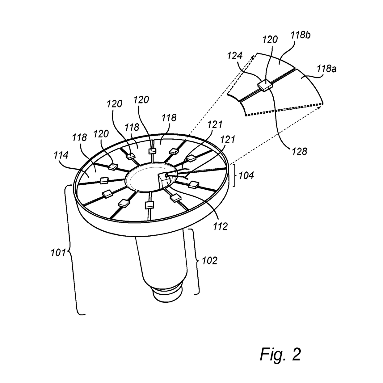
[0037]With reference to FIG. 1, a lighting device according to an embodiment will be described. FIG. 1 illustrates, in a perspective view, a lighting device according to an embodiment of the invention in an assembled view and in an exploded view. The lighting device 1 viewed to the left is an assembled lighting device. An exploded view of the lighting device 1 is viewed to the right.

[0038]The lighting device 1 in FIG. 1 comprises a housing 101 divided into a hollow neck portion 102 and an annular collar portion 104 surround...


PUM


Abstract

A lighting device (100, 300) comprising a housing (101, 301) comprising a polymer material, the housing including an elongated hollow neck portion (102) and a collar portion (104) arranged at an end of the neck portion. The collar portion includes an essentially annular surface (114, 414) surrounding the end of the neck portion peripherally. The collar portion has a metalized surface. The surface is structured into a plurality of electrically conductive pads (118, 318, 418) and the pads are electrically isolated from each other. A plurality of light emitting elements (120, 320, 420) are arranged on the collar portion of the housing. Each of the light emitting elements has a first terminal (128) electrically connected to a first electrically conductive pad (118a, 418a) and a second terminal (124) electrically connected to a second electrically conductive pad (118b, 418b). The collar portion is directly in contact with the surroundings, promoting an improved heat transfer from the light emitting elements. The lighting device further comprises an annular lens (108) arranged to cover the collar portion and configured to refract light from the light emitting elements.

Description

FIELD OF THE INVENTION[0001]The present invention generally relates to heat management and an improved housing in lighting devices.BACKGROUND OF THE INVENTION[0002]Heat management is an important issue within the field of illumination and, in particular, within the field of solid state based illumination, such as illumination based on light emitting diodes, LEDs. Generally, when light is emitted by a light source, heat is generated. The heat generation is commonly an undesired effect since it can affect performance and life expectance of the light sources, as well as the choice of materials and the configuration of electronics for the lighting device.[0003]In order to reduce the effects of the heat generation, lighting devices normally comprise a heat sink arranged to dissipate heat from the light sources and other heat generating components, typically in the direction opposite to the main (or average) light propagation direction of the lighting device. US2013 / 0082600 discloses an L...

Claims


Application Information

Patent Timeline
Patent Type & Authority Applications(United States)
IPC IPC(8): F21V29/503F21V15/01F21V29/70F21V3/02F21V23/00
CPCF21V29/503F21V3/02F21V15/01F21V29/70F21V23/003F21K9/232F21K9/238F21V5/00F21V23/009F21Y2103/33F21Y2115/10H01L25/0753H01L33/62H01L2224/49171
Inventor JIANG, QINGQINGYUAN, CHUANLI, LIN NAN
Owner SIGNIFY HLDG BV
Why Eureka
Try Eureka