Array Antenna for Measurement-While-Drilling

a technology of array antenna and drill collar, which is applied in the direction of protective material radiating elements, instruments, subaqueous/subterranean adaption, etc. it can solve the problems of increasing tool production and maintenance costs, reducing mechanical tool strength, and unable to distinguish resistivity changes in the coils aligned with the tool axis, so as to reduce the strength of the drill collar, reduce the structural integrity, and protect the drill collar from abrasion and other damag

Active Publication Date: 2008-09-18
WEATHERFORD TECH HLDG LLC
View PDF16 Cites 134 Cited by
  • Summary
  • Abstract
  • Description
  • Claims
  • Application Information

AI Technical Summary

Benefits of technology

[0010]The present invention is a MWD or LWD wave propagation resistivity logging system using an antenna comprising an array of cross-dipole elements with each element having cross magnetic dipoles. The array antenna concept provides a robust design that does not significantly reduce the structural integrity of a borehole drilling tubular or “mandrel” in which it is disposed. The array antenna and associated control and process methodologies are ideally suited for MWD or LWD systems. The disclosed apparatus and methods can, however, be applied to tools conveyed into the well borehole by other means such as wireline, tubing, slick line, and pump-down. Embodied as a MWD or LWD tool, the array design is robust is integrated into a drill collar body, and, in one preferred embodiment, requires only four “slots” in the form recesses in the drill collar per array antenna. The antenna elements are disposed in these recesses in the body of the drill collar, and are thereby protected by from abrasion and other damage caused by the rotation or longitudinal movement of the drill string to which the tool is attached. Because the recesses do not extend around the periphery of the drill collar, they do not significantly reduce the strength of the drill collar. The antenna elements comprise a plate composed of a soft ferromagnetic material crossed or looped by separate and independent current carrying conductors, such as wires, in two or more directions forming preferably a bi-directional or crossed magnetic dipole. The soft ferromagnetic material is preferably ferrite. The wires and elements of the array may be individually operated or connected together to produce a triaxial common origin magnetic dipole antenna. In addition, the versatility provided by the antenna design allows the antenna to operate in other useful modes, such as a quadrupole mode, circularly polarized mode, or a longitudinal current mode.

Problems solved by technology

Tools with coils aligned with the tool axis cannot distinguish resistivity changes as a function of tool azimuthal angle.
Furthermore, the antennas with different dipole orientations located at different axial spacings along the length of the tool lack a common dipole origin point.
Multiple antennas at differing axial spacings also increase tool production and maintenance cost, and further reduces mechanical tool strength.
It is well known in the art that reducing the outer diameter of a drilling collar weakens it in that area and causes the collar to be more prone to mechanical failure.
Non-conductive coverings presently used in the art such as fiberglass, rubber, epoxy, ceramics or plastic are subject to wear due to abrasion which occurs between the tool and the borehole wall, and are not as strong as the collar material.
Because the non-conducting region must encircle the collar it is likely to contact the borehole wall unless the collar is further “necked down” causing further weakness.
While this may be appropriate for wireline applications, openings in the tool body in which a coil is placed will cause weakness in the tool body.
Embodied in a MWD or LWD system, the Chen and Barber design must somehow be modified to divert the mud away from the coils and the openings in the tool body thereby adding complexity and cost to the manufacture of the tool.
Another problem encountered in embodying the Chen and Barber design as an MWD or LWD system is that, owing to the required non-conductive covering which is disposed around the circumference of the tool, the coils are not protected from abrasion which occurs between the tool and the borehole wall during drilling.
However “necking down” in the region of the antennas will significantly reduce the tubular strength in that region, and the tool will therefore be more prone to failure downhole.
Although more robust, the Wisler patent does not teach varying the direction of the antenna dipole moment.

Method used


Image

  • Array Antenna for Measurement-While-Drilling
  • Array Antenna for Measurement-While-Drilling
  • Array Antenna for Measurement-While-Drilling

Examples


Embodiment Construction

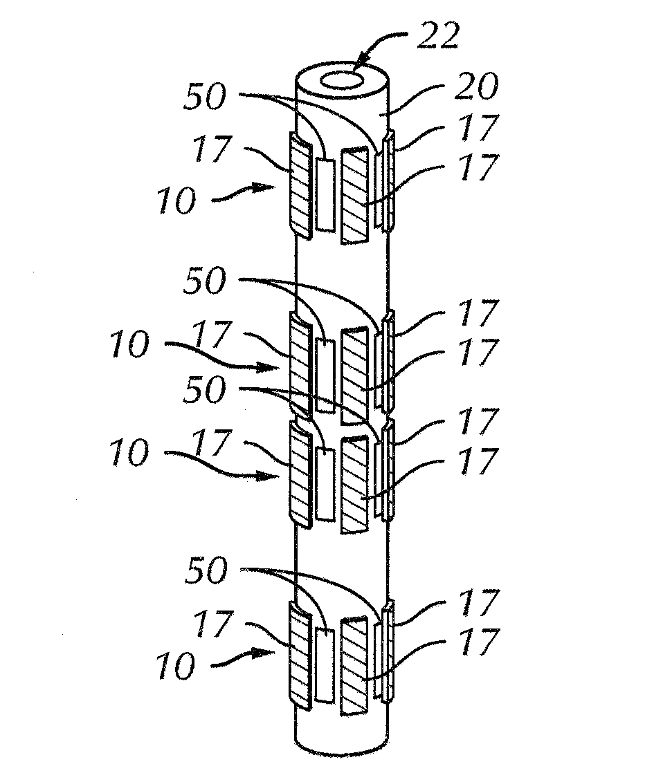
[0050]The present invention is described herein as a MWD or LWD wave propagation resistivity logging system comprising an integrated dipole array antenna. For brevity, both MWD and LWD systems will be referred to as “MWD” systems. The array antenna comprises several array elements that can act alone or in combination to produce a variety of measurement modes. Each array element is a cross-dipole element having cross magnetic dipoles. The dipole antenna components are used as both transmitters and receivers. Subsequent descriptions of antenna operation in a transmission mode apply equally to antenna operation in a reception mode. It will be realized by those familiar with the art that all of the magnetic dipole based antennas discussed in this disclosure can operate in either a transmission mode or a reception mode.

[0051]In a transmission mode, magnetic dipoles are generated by controlling, preferably with a numerically controlled oscillator (NCO) cooperating with a processor, the ph...


PUM


Abstract

An electromagnetic antenna for Measurement-While-Drilling (MWD) applications is disclosed. The antenna can include several array elements that can act alone or together in various measurement modes. The antenna elements can be disposed in tool body recesses to be protected from damage. The antenna elements can include a ferrite plate crossed or looped by independent current carrying conductors in two or more directions forming a bi-directional or crossed magnetic dipole. Although disclosed as a MWD system conveyed by a drill string, basic concepts of the system are applicable to other types of borehole conveyance.

Description

[0001]This invention is directed toward measurements made within a borehole, and more particularly directed toward an electromagnetic measurement-while-drilling (MWD) or a logging-while-drilling (LWD) system comprising at least one array antenna.BACKGROUND OF THE INVENTION[0002]A measurement of electromagnetic (EM) properties of earth formation penetrated by a borehole has been used for decades in hydrocarbon exploration and production operations. The resistivity of hydrocarbon is greater than saline water. A measure of formation resistivity can, therefore, be used to delineate hydrocarbon bearing formations from saline water bearing formations. Electromagnetic borehole measurements are also used to determine a wide range of geophysical parameters of interest including the location of bed boundaries, the dip of formations intersecting by the borehole, and anisotropy of material intersected by the borehole. Electromagnetic measurements are also used to “steer” the drilling of the bor...

Claims


Application Information

Patent Timeline
Patent Type & Authority Applications(United States)
IPC IPC(8): G01V3/00
CPCG01V3/28H01Q1/04H01Q21/205H01Q9/20H01Q1/40G01V3/30H01Q1/22
Inventor WISLER, MACMILLAN M.THOMPSON, LARRY WAYNEWU, JIAN-QUNSPENCER, MICHAEL S.
Owner WEATHERFORD TECH HLDG LLC
Why Eureka
Try Eureka