
Device and method for field xpansion

a field expansion and device technology, applied in the direction of cable junctions, manufacturing tools, connection formation by deformation, etc., can solve the problems of material cracks, insulation failure, and structural integrity decline, and achieve the effect of reducing the structural integrity of sleeves

Inactive Publication Date: 2014-04-10
3M INNOVATIVE PROPERTIES CO
View PDF1 Cites 4 Cited by
  • Summary
  • Abstract
  • Description
  • Claims
  • Application Information

AI Technical Summary

Benefits of technology

The patent describes a device and method that allows for expanding a field without compromising the strength of sleeves. The technical effect of this innovation is increased flexibility in field expansion without compromising the structural integrity of the device.

Problems solved by technology

However, the step portion decreases the structural integrity of the sleeve, and thus, in practice, stress concentration may occur at the step portion which can cause cracks in the material and lead to insulation failure.
However the configuration of some sleeves for pre-loaded cold shrink and some sleeves for push-on make it difficult or infeasible to expand such kind of sleeves on site by conventional field expansion methods.

Method used


Image

  • Device and method for field xpansion
  • Device and method for field xpansion
  • Device and method for field xpansion

Examples


Embodiment Construction

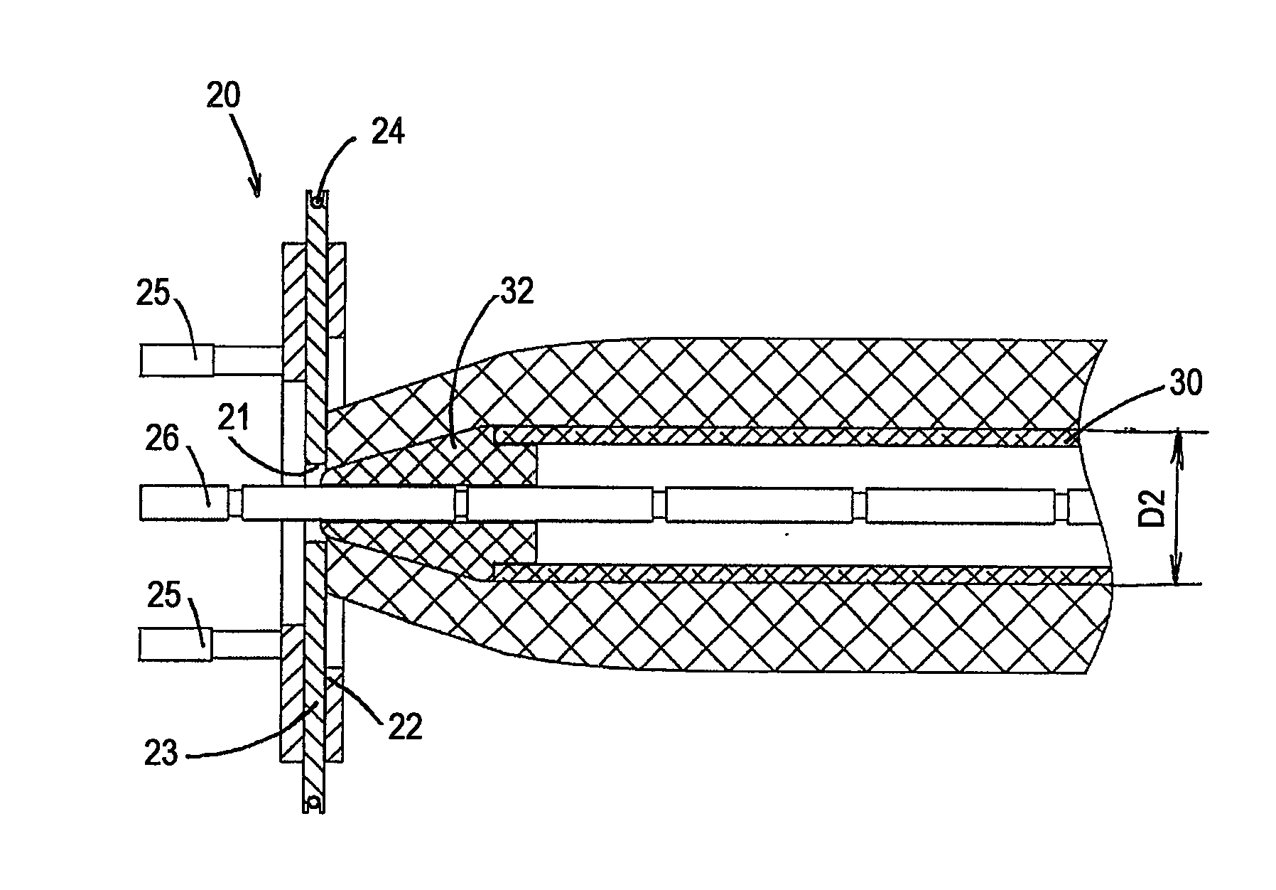
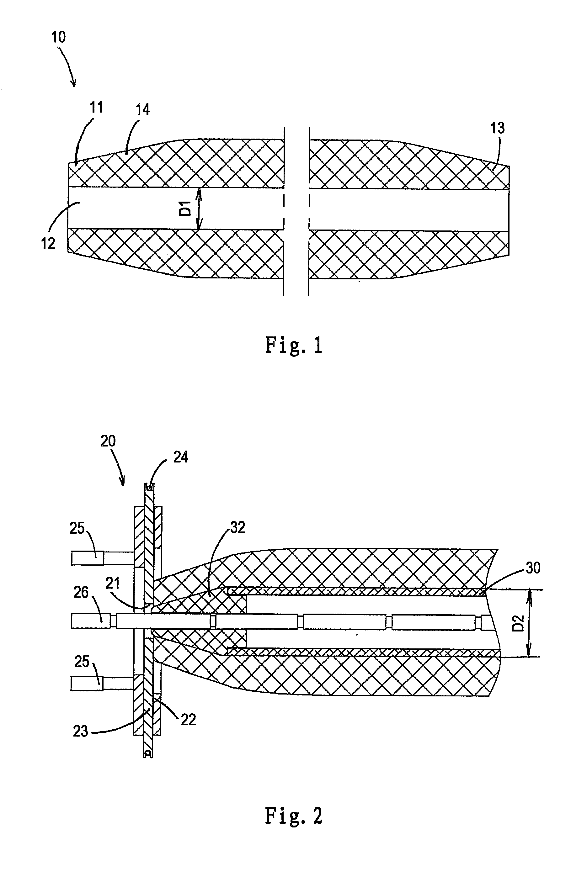
[0020]In the following detailed description of the preferred embodiments, reference is made to the accompanying drawings that form a part hereof. The accompanying drawings show, by way of illustration, specific embodiments in which the disclosure may be practiced. The illustrated embodiments are not intended to be exhaustive of all embodiments according to the disclosure. It is to be understood that other embodiments may be utilized and structural or logical changes may be made without departing from the scope of the disclosure. The following detailed description, therefore, is not to be taken in a limiting sense, and the scope of the invention is defined by the appended claims.

[0021]In the following Detailed Description, reference is made to the accompanying drawings, which form a part hereof, and in which is shown by way of illustration specific embodiments in which the invention may be practiced. In this regard, directional terminology, such as “left”, “right”, “top”, “bottom”, “...


PUM

PropertyMeasurementUnit
elongationaaaaaaaaaa
viscosityaaaaaaaaaa
friction coefficientaaaaaaaaaa

Abstract

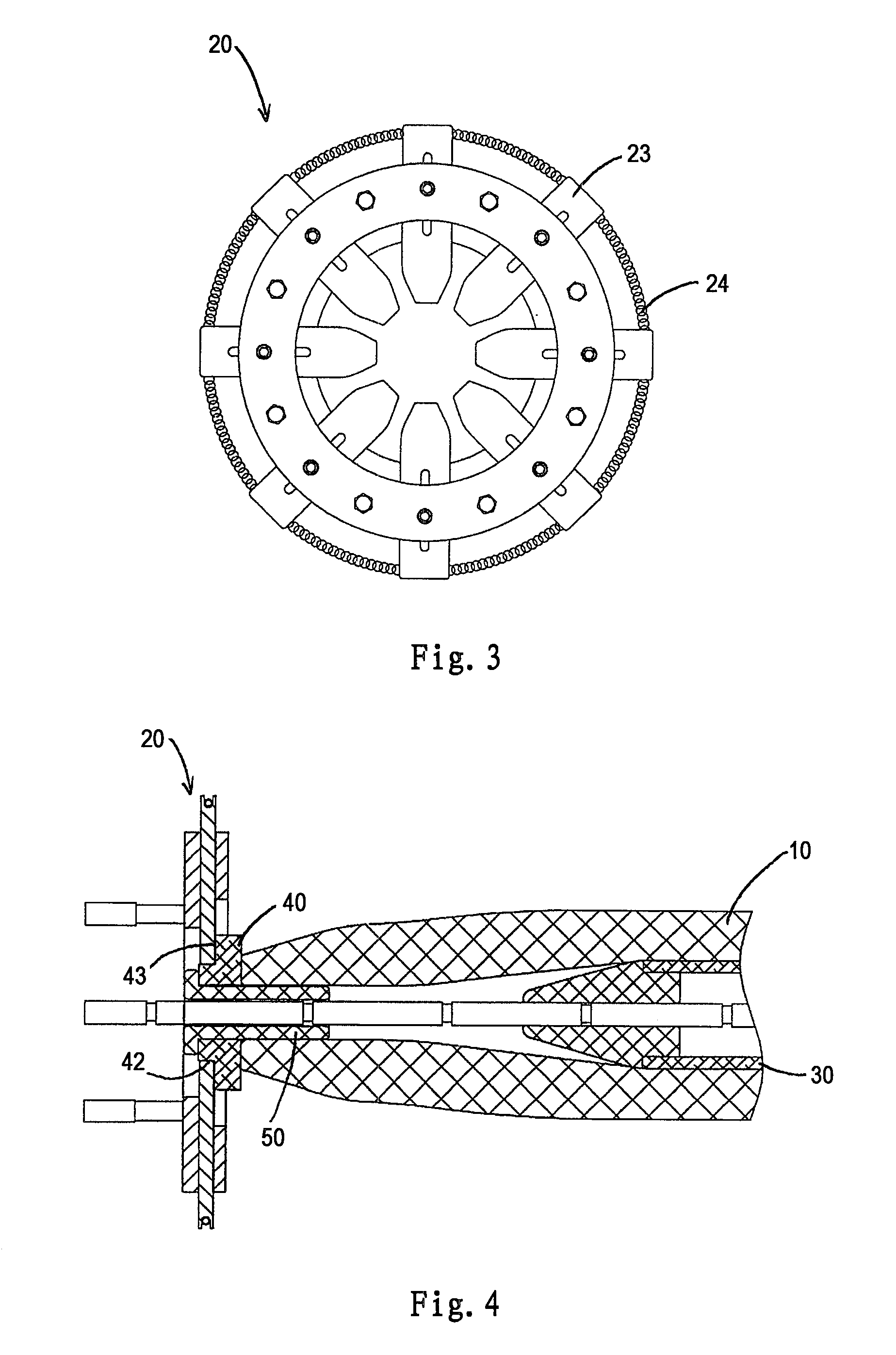
A device and a method for a field expansion. A support core (30) is inserted into the device by a field expansion apparatus. The field expansion apparatus has a pressure applying means (20) defining a radially expandable inner surface and a flat surface radially outwardly extending from the radially expandable inner surface. The device comprises an elastomeric tubing (10) and an adapter (40). The elastomeric tubing (10) has a forward end opposite a rearward end and an axial bore extending therethrough configured to receive the support core (30). The adapter (40) has a step portion (41) defined by a radial outer surface (42) and a flat surface (43) radially outwardly extending from the radial outer surface (42), and an axial bore (44) extending therethrough. The axial bore (44) has a diameter substantially the same as the diameter of the axial bore (12) of the elastomeric tubing (10). The adapter (40) is positioned substantially coaxially with the elastomeric tubing (10) between the pressure applying means (20) and the elastomeric tubing (10) such that, in response to inserting the support core (30) from the rearward end into the elastomeric tubing (10), the flat surface of the adapter (40) is pushed against the flat surface of the pressure applying means (20) by the elastomeric tubing (10); the interface between a rearward end of the adapter (40) and the forward end of the elastomeric tubing (10) is of high friction so that the adapter (40) and the elastomeric tubing (10) expand radially in unison, and the radial outer surface of the adapter (40) exerts a radially outward pressure against the radially expandable inner surface of the pressure applying means (20). device and method for field expansion device and method for field expansion

Description

FIELD OF THE INVENTION[0001]The disclosure relates generally to a device and method for field expansion, and particularly relates to a device and method for field expansion without decreasing structural integrity.BACKGROUND OF THE INVENTION[0002]Field expansion is a known method for stretching an elastomeric sleeve on site before application of the sleeve over a substrate by inserting a support core with an outside diameter larger than an inside diameter of the sleeve therethrough so that the sleeve expands in the radial direction. After the support core with the sleeve stretched thereon is positioned around the substrate, the support core is removed to allow the sleeve to shrink and tighten over the substrate so that electrical, air and / or water insulation is achieved over the substrate. The substrate can be spliced cables, terminated cables or any other form that need to be insulated or protected.[0003]Conventional sleeves for field expansion on site typically comprise a step port...

Claims


Application Information

Patent Timeline
Patent Type & Authority Applications(United States)
IPC IPC(8): H02G15/18
CPCH02G15/1826B29C55/24B29C61/065B29C63/18B29K2021/00H02G15/182Y10T29/4987Y10T29/53391Y10T29/53657B29C57/02H01R43/04H02G1/14H02G15/18
Inventor ZHANG, MINGYANG, JINQUANHUANG, ZHENGXU, ZHIGANGMA, JIANGJIANG
Owner 3M INNOVATIVE PROPERTIES CO
Learn More