
Golf club hosel interface having bendable section for customizing lie and face angles

Inactive Publication Date: 2002-08-13
NIRVANA GRP L L C THE
View PDF6 Cites 25 Cited by
  • Summary
  • Abstract
  • Description
  • Claims
  • Application Information

AI Technical Summary

Benefits of technology

It is another object of the present invention to provide a hosel interface for customizing golf clubs, but without requiring an inventory of different hosel interfaces for numerous angle ranges and increments in both lie angle and face angle.
It is yet another object of the invention to provide a bendable hosel interface for customizing golf clubs, but without requiring a circumferentially grooved or slotted hosel which would otherwise reduce the structural integrity of the golf club to an unacceptable degree.

Problems solved by technology

Clearly, it can be highly disadvantageous to require such a large inventory of such prior art devices, particularly when each golf club manufactured to a particular combination of lie and face angle will use one of those devices and force its replacement in the full set.
Thus the total number of such hosel constructions that must be kept on hand to accommodate even a modest rate of sales, can become entirely too burdensome to be practical.
The hosel being cast of the same material as the rest of the clubhead makes it undesirable for bending as the hosel is heat-treated or hardened the same as the rest of the clubhead.
This is a problem since making the hardness range soft enough to bend the hosel will allow the club face to cave-in when the golf ball is struck.
Conversely, making the hardness in a range to prevent face cave-ins makes the hosel brittle and very susceptible to fracturing during bending.
Unfortunately, a circumferential grooved or slotted hosel is inherently weaker and thus susceptible to fracture while making adjustments or hitting the golf ball.
The result can be catastrophic failure permitting the clubhead to separate from the shaft during a swing, which could cause serious injury to the golfer or others in proximity of the golfer.
However, unlike the prior art, there is no circumferential groove or slot in the hosel to weaken it and increase the risk of fracture that could cause separation of the clubhead from the shaft.

Method used


Image

  • Golf club hosel interface having bendable section for customizing lie and face angles
  • Golf club hosel interface having bendable section for customizing lie and face angles
  • Golf club hosel interface having bendable section for customizing lie and face angles

Examples


Embodiment Construction

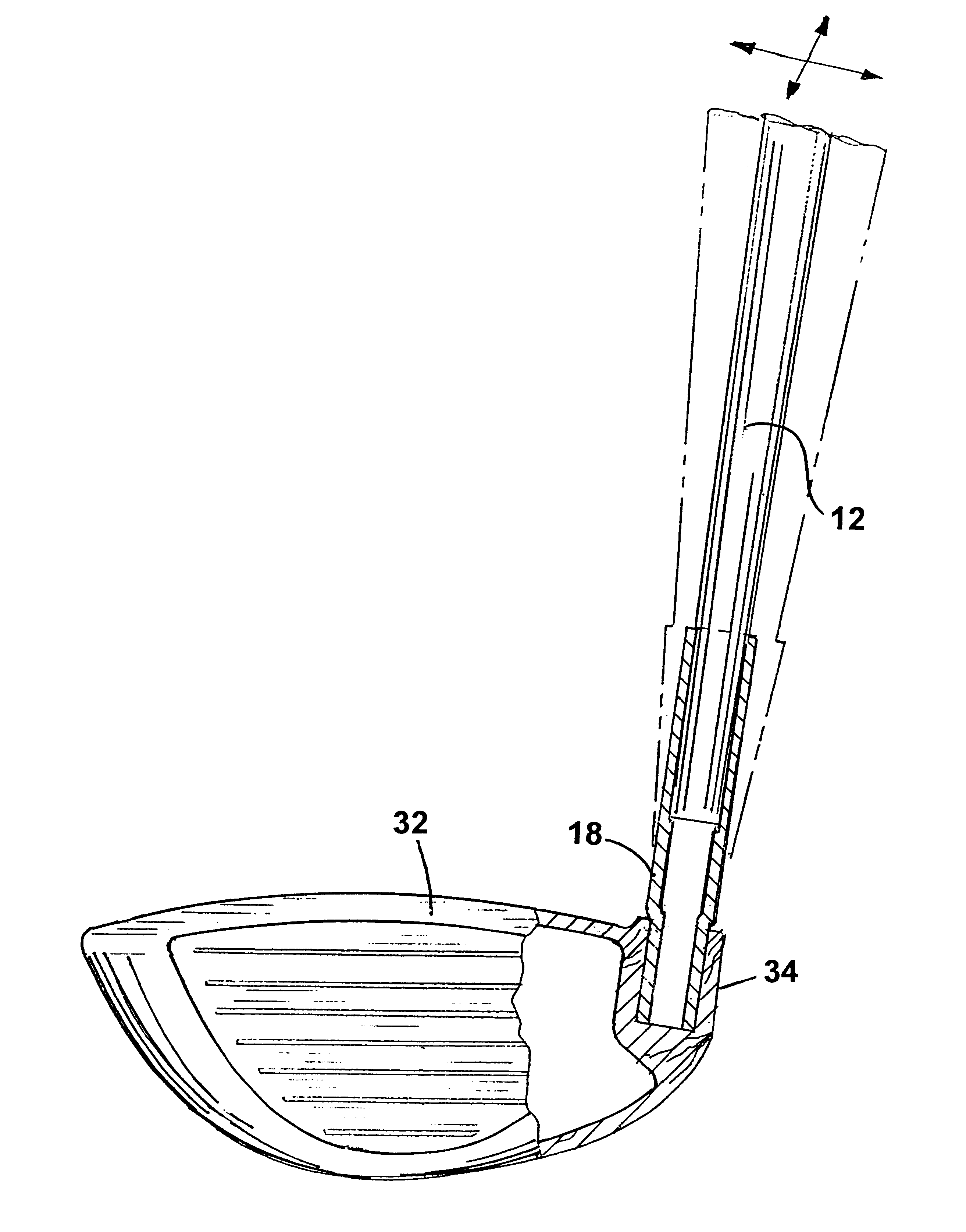
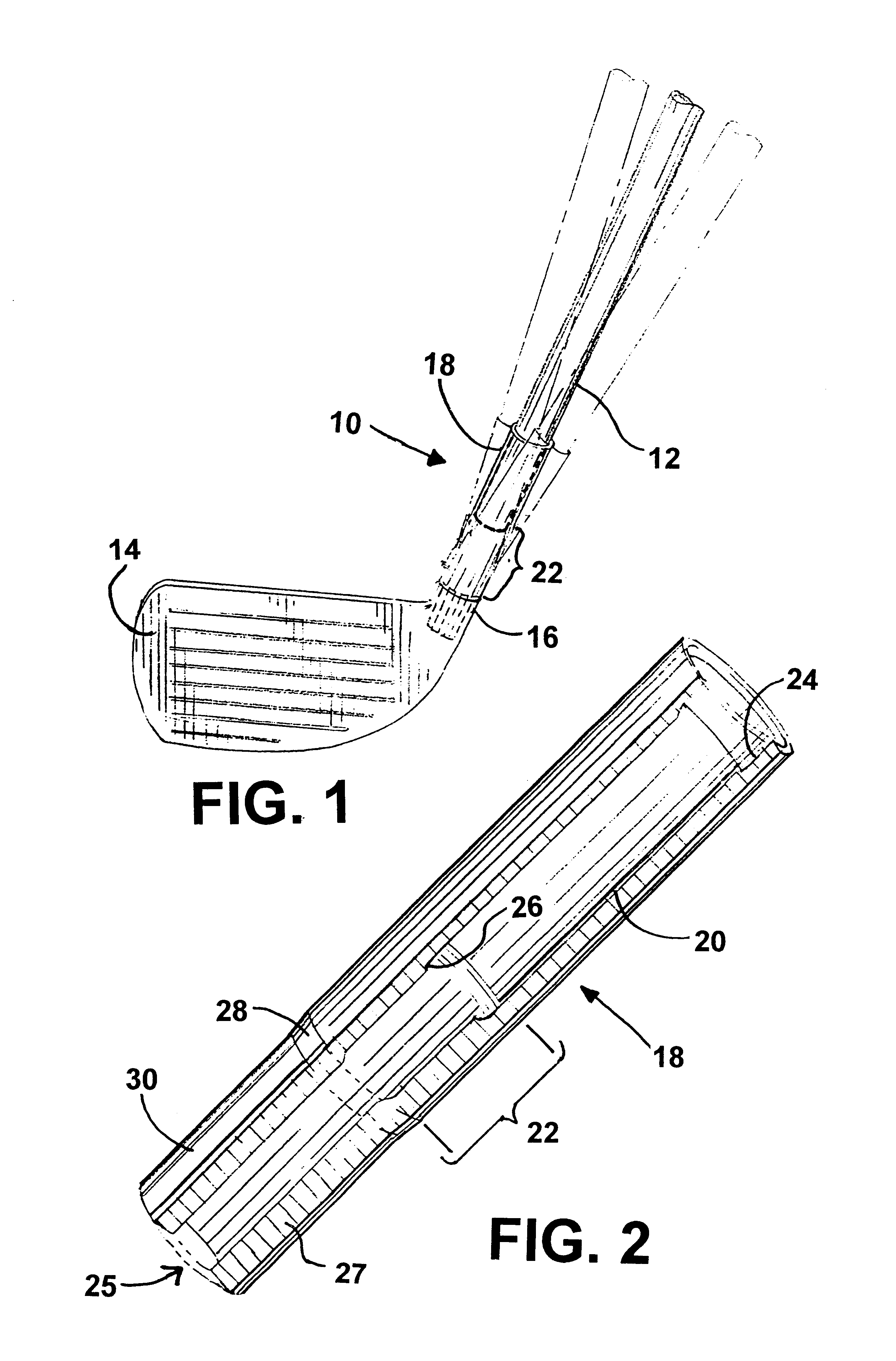
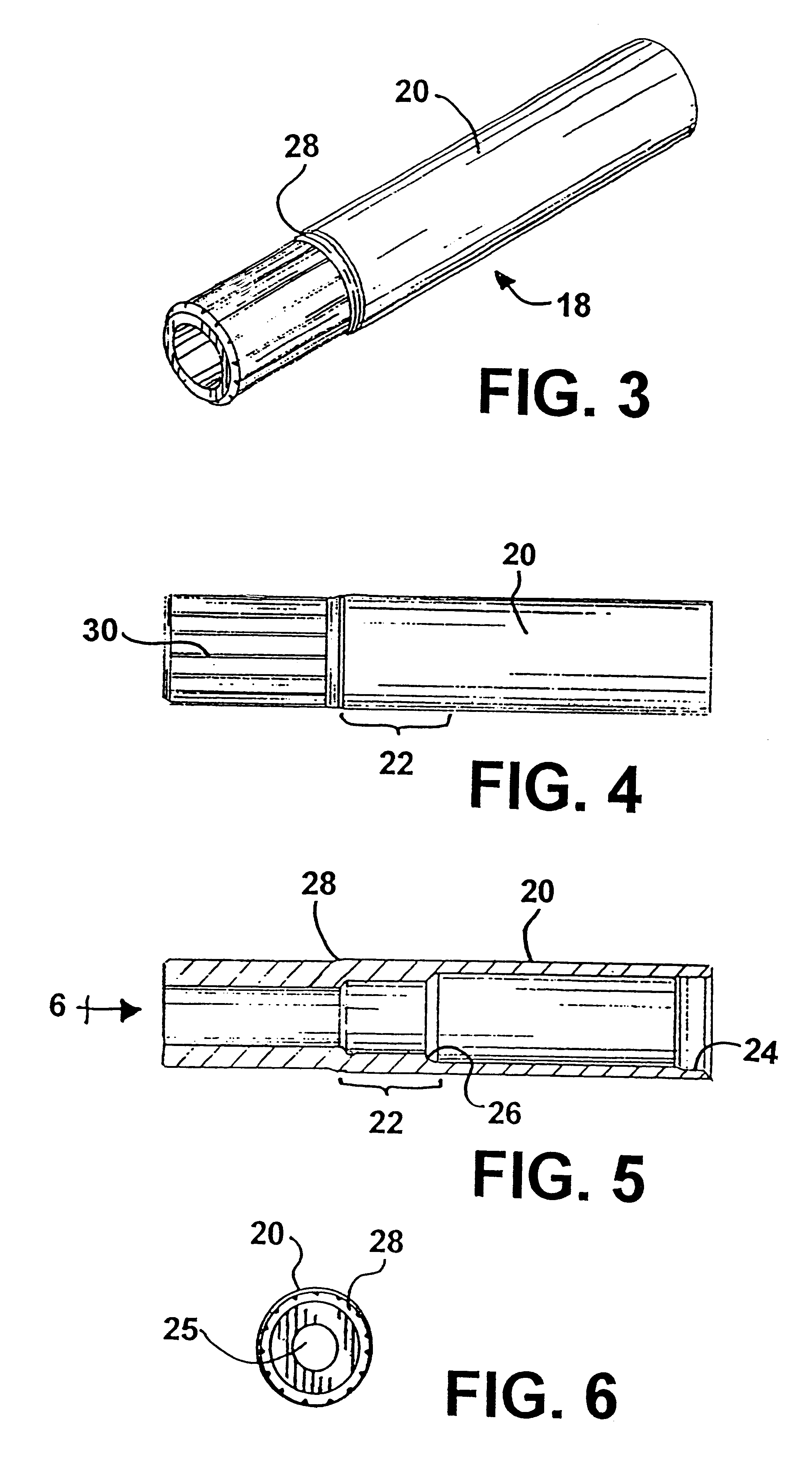
Referring to the accompanying figures, it will be seen that a golf club 10 comprises a shaft 12 and a golf club head 14 having a hosel 16. The shaft 12 and hosel 16 are interconnected by a hosel interface 18. Hosel interface 18 is an elongated hollow cylinder having an interior chamber 25 and comprises a shaft receptacle 20, an integral bendable section 22 and an insertable section 27.

The shaft receptacle 20 has a lead in 24 to facilitate receiving the shaft 12 and an interior shoulder 26 to seat the end of the shaft. An exterior shoulder 28 separates the shaft receptacle 20 and the bendable section 22 from the insertable section 27, the latter having a thickened wall thickness and a plurality of axial score lines 30 to facilitate connection to the hosel 16. By way of example, in FIG. 1 shaft 12 is shown in solid line at one angle relative to head 14 and in phantom line at two opposing alternative angles relative to head 14. Each such alternative angle is achieved by bending the ben...


PUM


Abstract

A hosel interface device for interconnection of the golf club shaft and the golf clubhead, the device having a portion which is made intentionally bendable to provide any desired extent of variation in lie angle and face angle in virtually an infinite number of increments. The invention employs a bending region along a portion of an otherwise straight exterior hosel interface or coupling. The hosel interface is configured to be inserted into the typical hosel area location of a golf club head such as a wood or iron head. The hosel interface also provides an elongated receptacle for receiving the clubhead end of a shaft. The bending region is between the clubhead insertion region and the shaft receptacle region of the hosel interface.

Description

1. FIELD OF THE INVENTIONThe present invention relates generally to customized golf clubs which are configured to best suit a particular golfer. The invention relates more specifically to a golf club hosel interface having an intentionally bendable portion which permits selected variation in lie angle and face angle without requiring a large inventory of differently configured hosels and without increasing the risk of a fracture.2. PRIOR ARTRelevant prior art appears in U.S. Pat. No. 5,851,155 to Wood et al. This patent discloses a hosel construction having a plug member and a neck member. The plug member is secured in the golf club head. The neck member extends integrally from the plug member and receives the shaft. The hosel construction is provided in numerous different configurations to provide different lie and face angles. As shown in column 5, lines 49-60, in order to offer deviations of lie angles and face angles which are in the angular range of only + or -1 degree incremen...

Claims


Application Information

Patent Timeline
IPC IPC(8): A63B53/02A63B53/06
CPCA63B53/02A63B53/06A63B2053/022A63B53/0487A63B53/047A63B2053/0408A63B53/0466A63B53/022A63B53/0408A63B60/0085
Inventor DYER, ALONZO J.
Owner NIRVANA GRP L L C THE
Learn More