Method, System, and Apparatus to Prevent Electrical or Thermal-Based Hazards in Conduits

a technology of electrical or thermal-based hazards and conduits, applied in static indicating devices, protective switch details, instruments, etc., can solve problems such as hazards affecting the safety of conduits, and achieve the effects of reducing the risk of dc arcs, avoiding dc arcs, and avoiding dc arcs

Inactive Publication Date: 2018-10-04
MANAGEMENT SCI
View PDF1 Cites 0 Cited by
  • Summary
  • Abstract
  • Description
  • Claims
  • Application Information

AI Technical Summary

Benefits of technology

[0028]The following summarizes advantages of the present invention over prior art. 1) The present invention provides means to utilize the ohmic heating phenomena which is symptomatic of progression leading to an electrical arc fault at a higher temperature; 2) can be added during manufacturing of the connector; 3) can be plugged-in during installation of connectivity; 4) can be added after the connectivity is installed to provide protection to existing systems; 5) has no electronic circuit which could fail; 6) has no electrical or mechanical contacts that make and break the connection; 7) can be embodied to cause disruption and eliminate further risk; 8) is easy to install or integrate into the connectivity. 9) is immune to producing false alarms due to naturally occurring RF emissions; 10) operates before there is a significant precursor change in voltage or current produced by an arc event; 11) is able to operate when repeated hot / cold cycles result in very low ampere electrical discharges across a sub-millimeter sized gap at joints within the connectivity component such as due to a factory defect in the connectivity component; or an installer does not make a proper connection causing a gap in the joint small enough to cause a self-extinguishing discharge which will subsequently result in an arc fault with associated high-temperature plasma energy.
[0029]The present invention differentiates from electrical arc fault protection devices that operate by detecting noise, radio frequency, light of plasma, or electromagnetic emissions of a discharge. The present invention also differentiates from electrical arc fault protection devices that operate by thermomorphic principles and thermokinetic principles to detect heat of an active arc or a fire. Additionally, such existing means are not-proactive.
[0030]The present invention differentiates from prior art in that it detects an electrical arc-fault by utilizing the thermovolumetric force generated by the heat associated with the hazardous condition to subsequently disrupt the flow.
[0031]The present invention omits the need for electronic modules and sensors used to recognize the artifacts of a live electrical arc fault, such as a flash of plasma, radio frequency emissions, current rise, or simultaneous voltage drop.
[0032]An advantage exists over thermal pellet-based thermal fuse designs in that thermal pellet based designs require a high degree of structural integrity from the thermal pellet as the thermal pellet acts as a structural barrier during normal operation of a thermal fuse. Furthermore, thermal fuses are produced for relatively low operating current and voltage. No indication is visible when a thermal fuse has activated, making troubleshooting more cumbersome.
[0033]The present invention has an advantage over designs which contain springs. Springs apply a constant force to the walls and components within the body of a design. Spring-based devices require higher structural integrity and the spring can also act as a pathway for electricity to flow in the event of a severe arc fault. Elevated temperature conditions can further affect the lifetime of spring containing devices as the structural integrity of a spring containing body is significantly reduced at regional hot weather temperatures.

Problems solved by technology

The relationship means that either increased resistance or increased current would eventually result in a DC arc with the hazards.

Method used


Image

  • Method, System, and Apparatus to Prevent Electrical or Thermal-Based Hazards in Conduits
  • Method, System, and Apparatus to Prevent Electrical or Thermal-Based Hazards in Conduits
  • Method, System, and Apparatus to Prevent Electrical or Thermal-Based Hazards in Conduits

Examples


Embodiment Construction

[0058]Various embodiments of the invention are disclosed in the following detailed description and accompanying drawings. Each drawing teaches how to implement the techniques and / or components to affect the purposes of this patent.

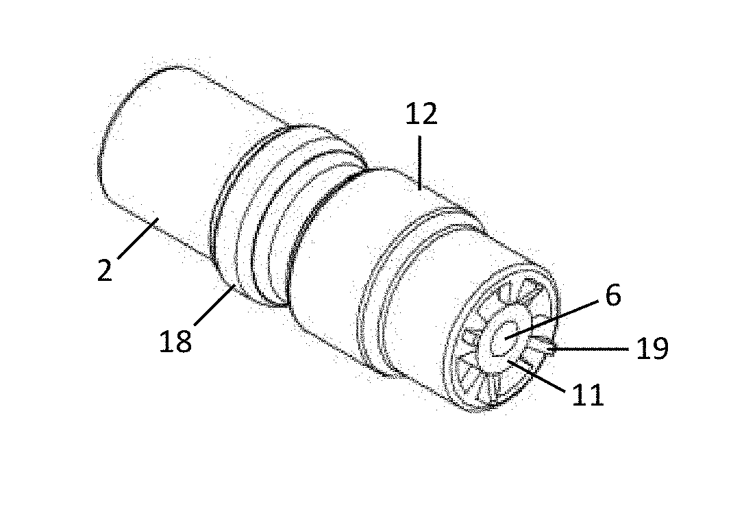
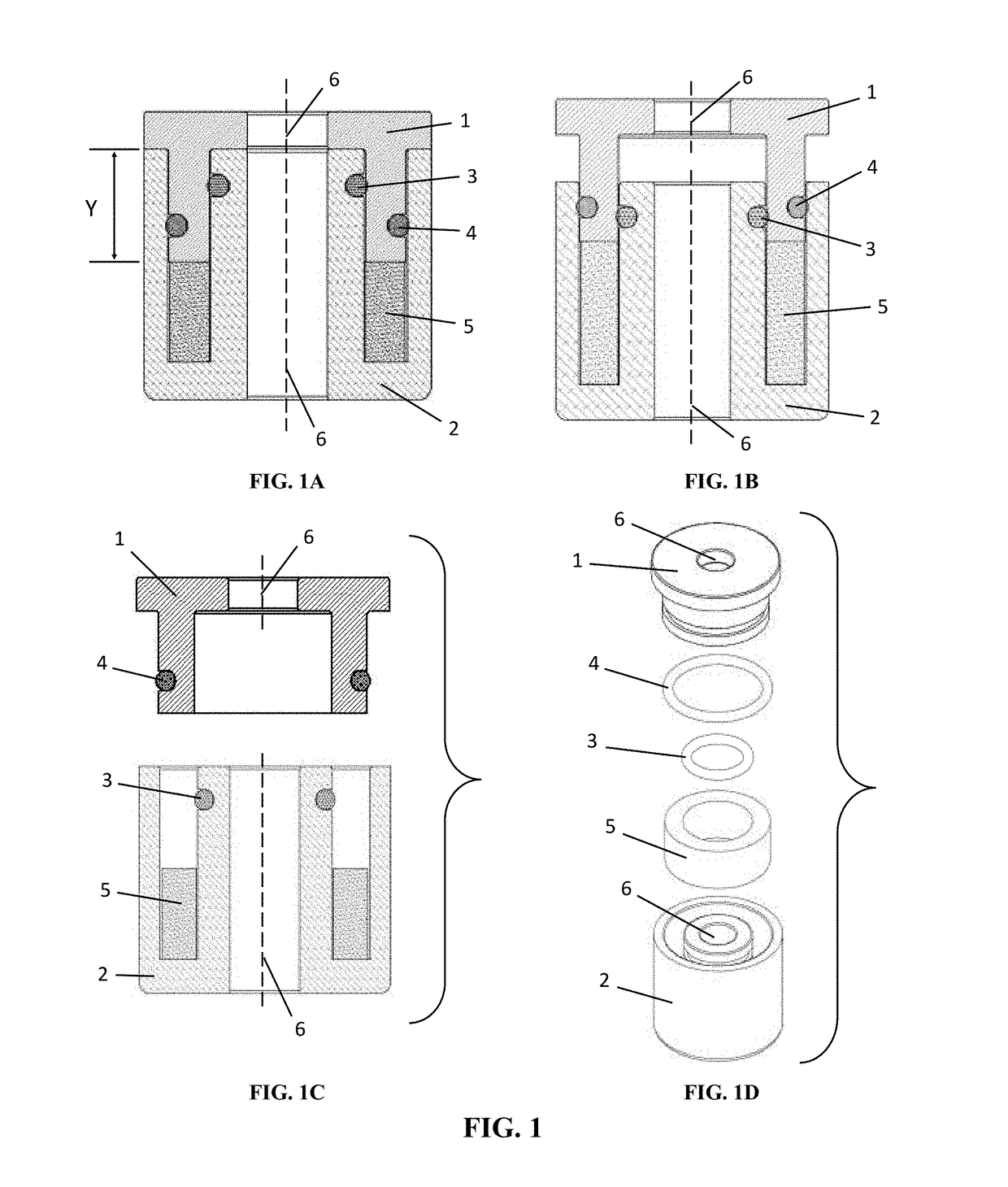
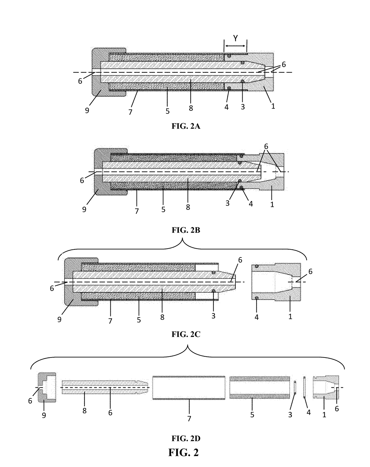
[0059]FIG. 1 is a cutaway assembly drawing with four sub-drawings that depict an embodiment of the current invention. FIG. 1A depicts a cutaway view of a fully assembled connectivity design where a thermovolumetric substance is enclosed within the connectivity body. The image teaches how the components of the connectivity will be arranged when fully assembled. A total of five components are used in the assembly of this connectivity design. Two components comprise the main body of the connectivity, two components act as sealing mechanisms, while the final component is the thermovolumetric substance that expands upon heating. The dimension ‘Y’ represents the displacement distance which the thermovolumetric substance will cause the upper portion of the connec...


PUM

PropertyMeasurementUnit
pressureaaaaaaaaaa
pressureaaaaaaaaaa
diameteraaaaaaaaaa

Abstract

A method, apparatus, and system for protection from hazards of conductivity is disclosed using non-electrical means to disrupt electrical current with a thermovolumetric substance. The purpose of this invention is to prevent hazardous conditions from occurring by disrupting the flow of electrical current prior to the development of arc fault conditions.

Description

BACKGROUND OF THE INVENTION[0001]Systems which are in connectivity typically include an infrastructure comprised of mechanical framework and means for disconnecting, regulating, controlling, distributing, and modifying the conducted material. Electrical arc-faults in connectivity occur when the operating current exceeds normal bounds; such as caused by differences in expansion of the conduit and metal contacts, a manufacturing defect, or Ohmic heating caused by increased resistance of the conductor due to galvanic corrosion.[0002]Electrical arc faults in electrical connectivity generate white hot plasma and intense heat. Arc faults can be caused, for example, by a manufacturing defect, overload, or thermal expansion and contraction at the joints by the thermodynamics of current on the conductor. There is a plethora of publically available documents such as, “American Electricians Handbook” by T. Croft, F. Hartwell, and W. Summers (which is included in its entirety by reference herei...

Claims


Application Information

Patent Timeline
Patent Type & Authority Applications(United States)
IPC IPC(8): H01H71/10H01H71/02G02F1/133G02F1/1345G09G3/20G09G3/36G11C19/00G11C19/28
CPCH01H71/02H01H71/10H01H37/74H01H71/14H01H2071/147G02F1/13624G09G3/3677G09G3/3688G09G2300/0417G09G2320/043G09G2330/021G11C19/28H01L27/1255H01L29/42384H01L29/78696G02F1/133345G02F1/134309G02F1/13454G02F1/136286G02F1/1368G02F2202/103G09G3/3266G09G2300/0426G09G2330/023H01L27/105H01L27/12H01L27/1214H01L27/1222H01L27/124H01L27/1251H01L27/13H01L29/78663H01L29/78678H10K59/131H10K59/1213
Inventor BLEMEL, KENNETH GERALDBLEMEL, KENNETH DOMINICBONE, BENJAMIN ALLENADAMCZYK, JESSE MIN-TZEDRAELOS, LARA ROSEFLORES-OLIVAS, MARIANAHINTON, MATTHEW JAMES
Owner MANAGEMENT SCI
Why Eureka
Try Eureka