Steerable magnetic dipole antenna for measurement while drilling applications

a magnetic dipole antenna and drilling technology, applied in wave based measurement systems, instruments, reradiation, etc., can solve the problems of non-conducting materials used to cover antenna elements that are not as resistant to wear and gouging as steel and other conductors, and achieve the effect of reducing the structural integrity of the tool body

Active Publication Date: 2011-04-14
WEATHERFORD TECH HLDG LLC
View PDF8 Cites 12 Cited by
  • Summary
  • Abstract
  • Description
  • Claims
  • Application Information

AI Technical Summary

Benefits of technology

[0012]The present invention describes a robust, steerable, magnetic dipole antenna for Measurement-While-Drilling (MWD) or Logging-While-Drilling (LWD) applications. The antenna elements use a hole arrangement in addition to grooves in a steel tool body, which is typically a drill collar. This antenna embodiment produces an extremely robust, antenna that does not significantly reduce the structural integrity of the tool body in which it is disposed. The antenna embodiment is also wear resistant in harsh MWD or LWD environments, as will be illustrated in detail in subsequent sections of this disclosure. Also the resultant magnetic dipole generated by this antenna is not generated by a wire disposed in a single plane as the prior art and is thereby electrically steerable in inclination angle from a common origin. A variable dipole moment inclination angle combined with independently measured tool rotation orientation during normal drilling allows the antenna to generate a magnetic dipole moment that may be directed at any three dimensional angle and from a common origin point at the centroid of the antenna. In the context of this disclosure, “inclination angle” is the angle that the antenna magnetic dipole moment forms with the tool axis.

Problems solved by technology

In general, non-conducting materials used to cover antenna elements are not as resistant to wear and gouging as steel and other conductors.

Method used


Image

  • Steerable magnetic dipole antenna for measurement while drilling applications
  • Steerable magnetic dipole antenna for measurement while drilling applications
  • Steerable magnetic dipole antenna for measurement while drilling applications

Examples


Embodiment Construction

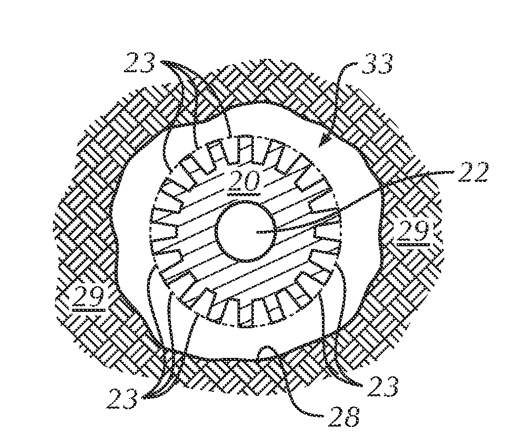
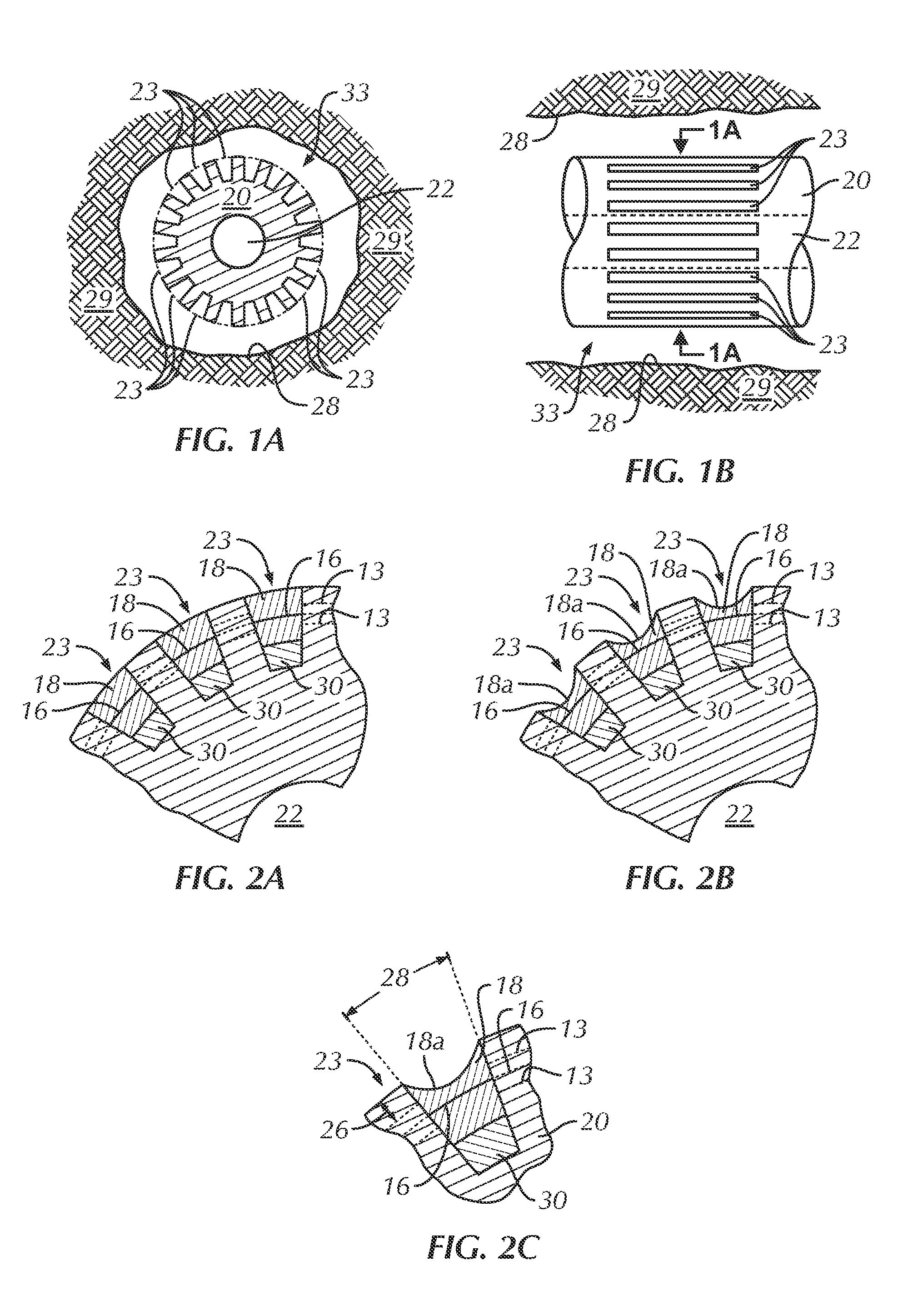
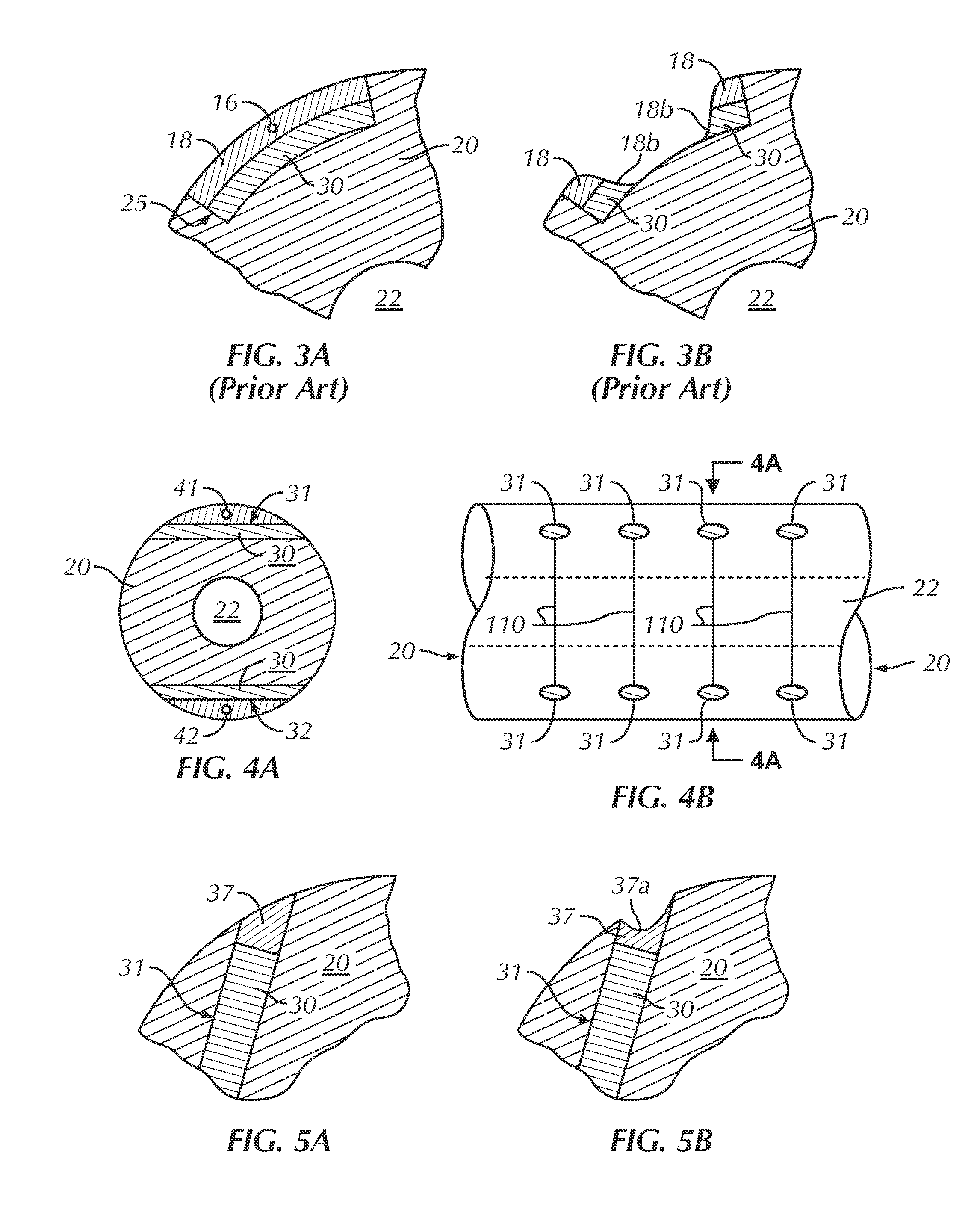
[0042]The present invention describes a robust, steerable, magnetic dipole antenna for 10 kilohertz (kHz) to 10 megahertz (MHz) Measurement-While-Drilling (MWD) or Logging-While-Drilling (LWD) applications. The antenna elements comprise one or more antenna “hole” elements in addition to one or more antenna “groove” elements in a steel tool body, which is typically a drill collar. This embodiment produces an extremely robust antenna that does not significantly reduce the structural integrity of the tool body in which it is disposed. The antenna embodiment is also relatively wear resistant to the harsh MWD or LWD environments. For brevity, both MWD and LWD systems will be referred to as “MWD” systems.

[0043]Using antenna hole elements perpendicular to the tool axis only, a magnetic field can be generated or received perpendicular to the major axis of the tool. Using groove elements parallel to the tool axis only a magnetic vector can be generated or received parallel to the major axis ...


PUM


Abstract

A steerable, magnetic dipole antenna for Measurement-While-Drilling (MWD) or Logging-While-Drilling (LWD) applications. The antenna elements use a hole arrangement in addition to grooves in a steel tool body, which is typically a drill collar. This antenna embodiment is extremely robust, meaning that does not significantly reduce the structural integrity of the tool body in which it is disposed. The antenna embodiment is also relatively wear resistant. The resultant magnetic dipole generated by this antenna is also electrically steerable in inclination angle from a common origin. A variable dipole moment inclination angle combined with independently measured tool rotation orientation during normal drilling allows the antenna to generate a magnetic dipole moment that may be directed at any three dimensional angle and from a common origin point at the centroid of the antenna.

Description

FIELD OF THE INVENTION[0001]This disclosure is directed toward a robust, steerable, magnetic dipole antenna for Measurement-While-Drilling (MWD) or Logging-While-Drilling (LWD) applications.BACKGROUND OF THE INVENTION[0002]A measurement of electromagnetic (EM) properties of earth formation penetrated by a borehole has been used for decades in hydrocarbon exploration and production operations. The resistivity of hydrocarbon is greater than saline water. A measure of formation resistivity can, therefore, be used to delineate hydrocarbon bearing formations from saline water bearing formations. Electromagnetic borehole measurements are also used to determine a wide range of geophysical parameters of interest including the location of bed boundaries, the dip of formations intersecting the borehole, and anisotropy of material intersected by the borehole. Electromagnetic measurements are also used to “steer” the drilling of the borehole.[0003]Borehole instruments, or borehole “tools”, used...

Claims


Application Information

Patent Timeline
Patent Type & Authority Applications(United States)
IPC IPC(8): G01V3/00
CPCG01V3/28G01B7/001
Inventor WISLER, MACMILLAN M.THOMPSON, LARRY W.WU, JIAN-QUNPATE, LANCE
Owner WEATHERFORD TECH HLDG LLC
Why Eureka
Try Eureka