
Method and apparatus to resist fading in mimo and simo wireless systems

a wireless communication and wireless technology, applied in wireless communication, multiplex communication, polarisation/directional diversity, etc., can solve problems such as negative affecting system performance, constructive and destructive interference, and face performance problems, and achieve the effect of reducing rf fading

Active Publication Date: 2009-07-21
REDWOOD TECHNOLOGIES LLC +1
View PDF29 Cites 6 Cited by
  • Summary
  • Abstract
  • Description
  • Claims
  • Application Information

AI Technical Summary

Benefits of technology

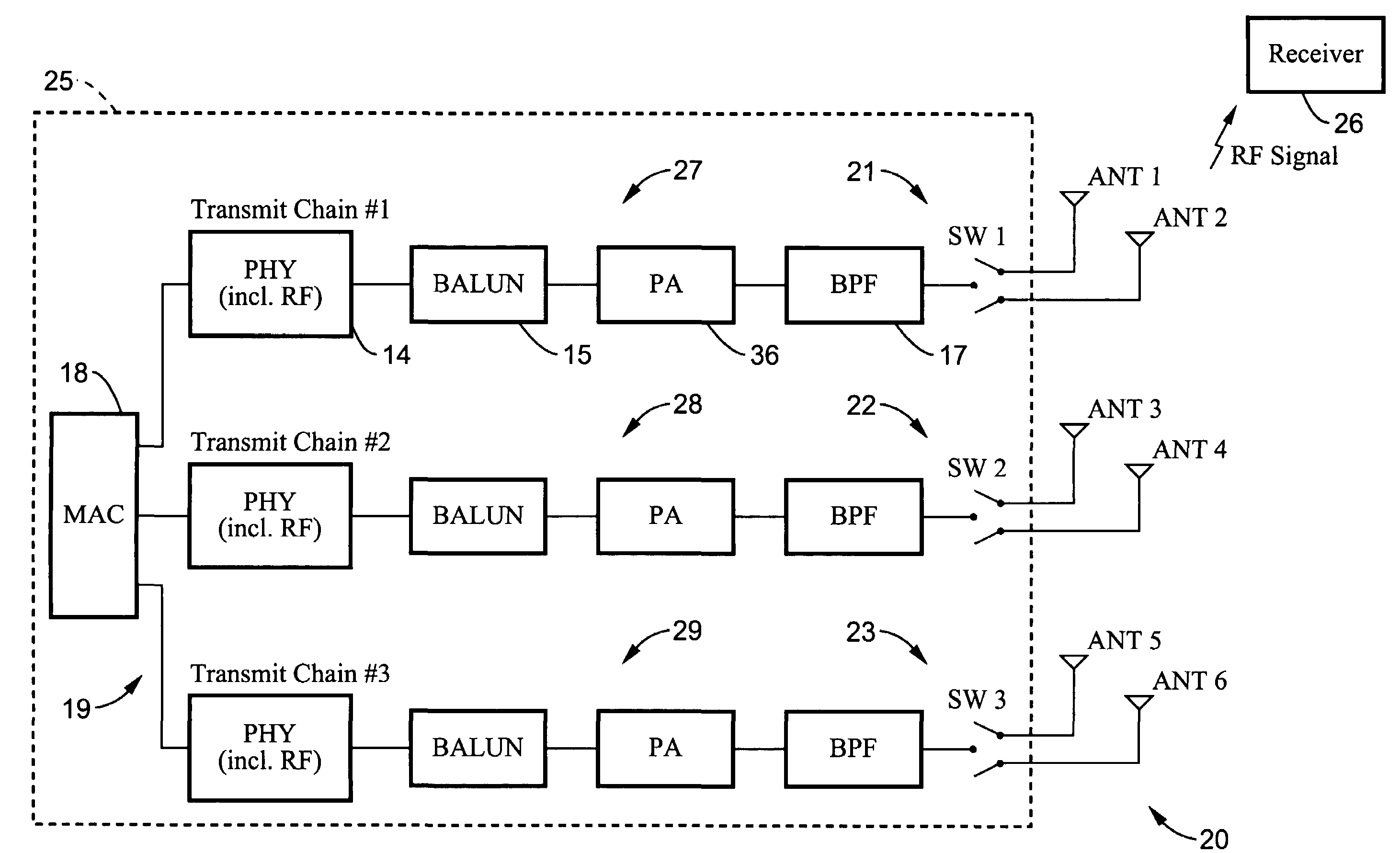
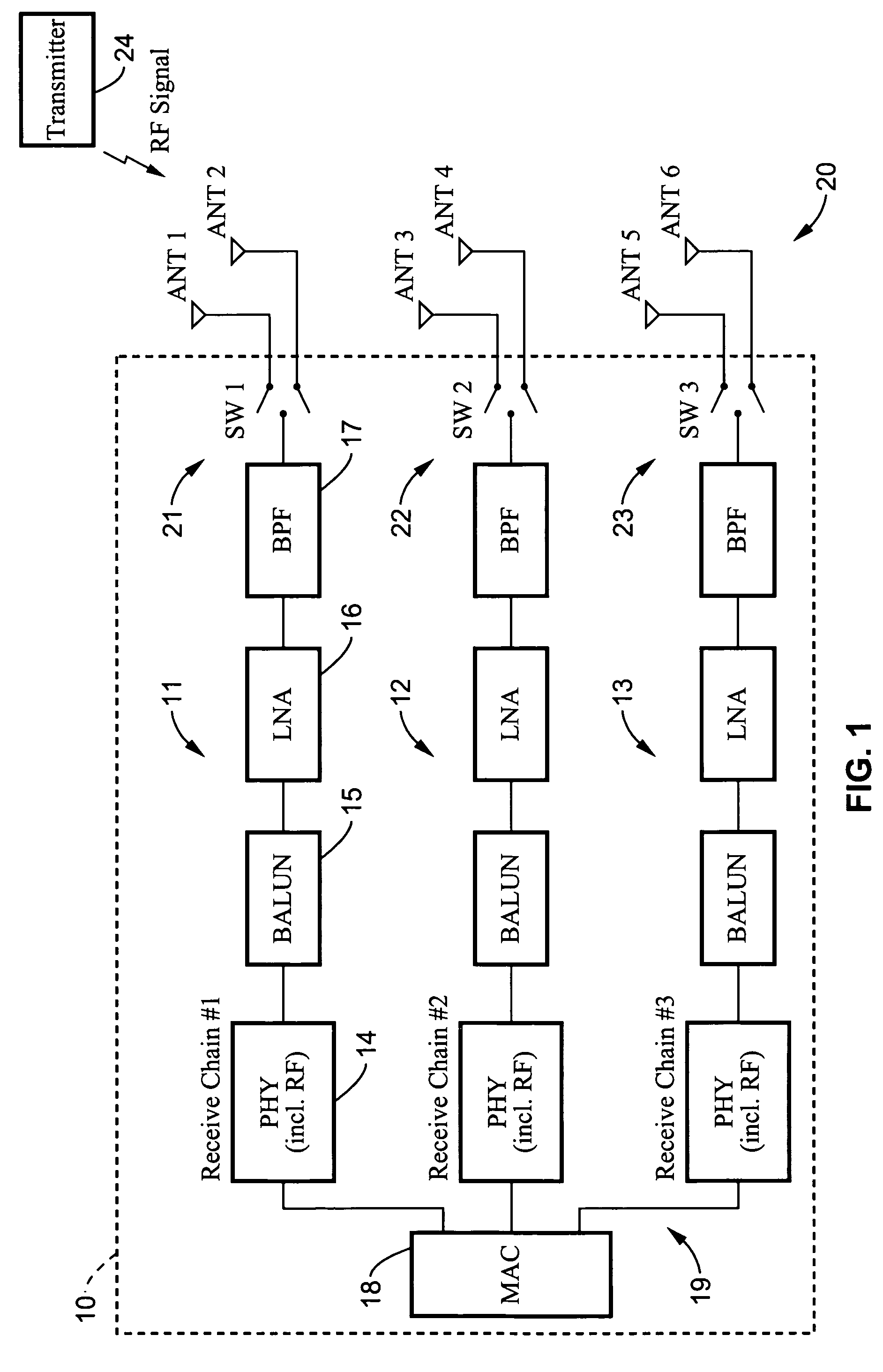
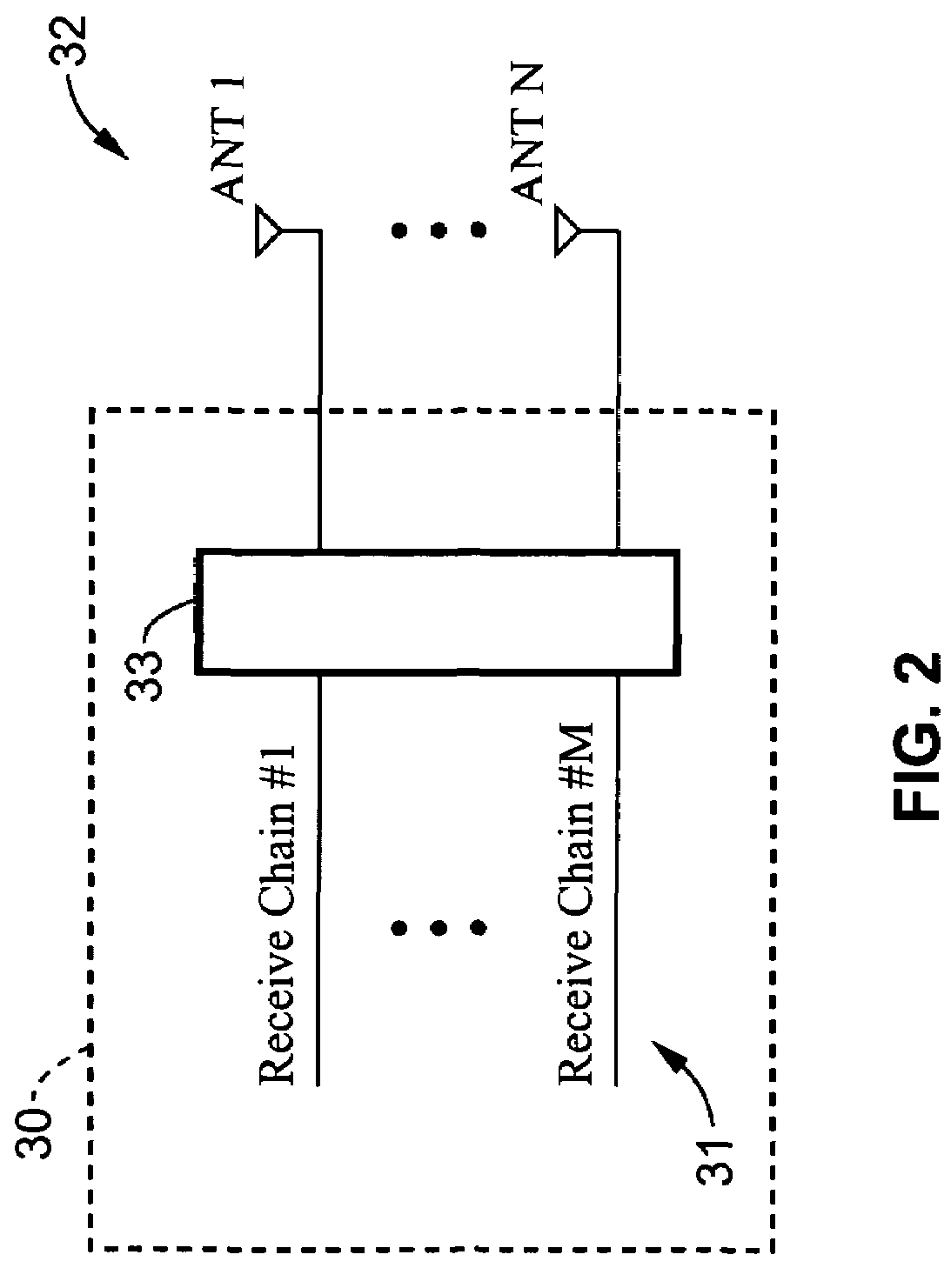
[0016]An aspect of the invention is a wireless communication apparatus having a transmitter for transmitting an RF signal and a receiver for receiving the RF signal. The receiver includes a first plurality of receive chains and a second plurality of antennas. Each receive chain is selectively connectable to selected antennas. The antennas are selected based on criteria obtained from a received RF signal to produce an antenna configuration connected to the receive chains to reduce RF fading at the receiver.
[0019]A further aspect of the invention is a wireless communication apparatus made up of a transmitter for transmitting an RF signal; a receiver for receiving the RF signal, the receiver including a first plurality of receive chains and a second plurality of antennas; means for selectively connecting each receive chain to selected antennas; and means for selecting the antennas to be connected to each receive chain based on criteria obtained from a received RF signal to produce an antenna configuration connected to the receive chains to reduce RF fading at the receiver.
[0020]A still further aspect of the invention is a method for reducing fading in a wireless communication system by providing a receiver having a first plurality of receive chains and a second plurality of antennas, selecting the best antenna to be connected to each chain based on criteria obtained from a received RF signal to produce an antenna configuration connected to the receive chains to reduce RF fading at the receiver, and connecting each receive chain to the selected antennas. The best antenna for each chain is selected by measuring characteristics of the received signal for each allowed antenna configuration and selecting the best antenna configuration.

Problems solved by technology

These systems all face performance problems associated with RF propagation.
Signal variation due to RF propagation problems will negatively affect system performance.
The causes of fading include constructive and destructive interference of RF due to multipath propagation, as well as the motion of objects in the environment.
RF fading is a problem for wireless systems based on technologies such as MIMO (Multiple Input, Multiple Output).
Ideally, the paths from each Tx antenna to each Rx antenna are uncorrelated while having sufficient signal to noise ratio (SNR) to allow reliable demultiplexing at the receiver.
However it is possible that the signal at one or more of the three antennas at the receiver will have a low SNR (Signal to Noise Ratio) and hence will be unable to support a desired data rate for the MIMO system (e.g. 72 Mbps) even though a few (e.g. three) inches away a signal with adequately high SNR may exist.
RF fading is also a problem for WLANs using coherent combination at the receiver, such as those employing Maximum Ratio Combining (MRC); these can be MIMO or SIMO (Single Input, Multiple Output) systems.
However this is not practical in cases where the receiver is part of a large immovable object, and is also not user-friendly since it is often unclear to even a mobile user exactly how or in which direction the receiver should be moved in order to improve performance.
However, the problem with this approach is that adding additional parallel processing chains is computationally complex, and adds many more components, and is hence more expensive and less compact to implement.

Method used


Image

  • Method and apparatus to resist fading in mimo and simo wireless systems
  • Method and apparatus to resist fading in mimo and simo wireless systems
  • Method and apparatus to resist fading in mimo and simo wireless systems

Examples


Embodiment Construction

[0029]Referring more specifically to the drawings, for illustrative purposes the present invention is embodied in the apparatus and methods generally shown in FIG. 1 through FIG. 5. It will be appreciated that the apparatus may vary as to configuration and as to details of the parts, and that the methods may vary as to the specific steps and sequence, without departing from the basic concepts as disclosed herein.

[0030]The invention applies to systems for the wireless RF propagation of signals, including particularly RF propagation of signals transmitted from 802.11 wireless local area networks (WLANs). The basic structures and operation of these types of systems is well known in the art. The systems include transmitters and receivers, or in combination transceivers, with associated antennas. The systems operate generally on various modulation and demodulation schemes. Information is typically transmitted in packets.

[0031]The transmitters and receivers of a wireless system can be con...


PUM


Abstract

In a wireless communication system the receiver includes a first plurality of receive chains and a second plurality of antennas. Each receive chain is selectively connectable to selected antennas. The antennas are selected based on criteria obtained from a received RF signal to produce an antenna configuration connected to the receive chains to reduce RF fading at the receiver. An electronic switch connects the antennas to the receive chains. The receiver is programmed to determine which antenna should be connected to each receive chain by the switch by measuring characteristics of the received signal for each allowed antenna configuration and selecting the best antenna configuration. Transmitters may be similarly configured.

Description

CROSS-REFERENCE TO RELATED APPLICATIONS[0001]Not ApplicableSTATEMENT REGARDING FEDERALLY SPONSORED RESEARCH OR DEVELOPMENT[0002]Not ApplicableINCORPORATION-BY-REFERENCE OF MATERIAL SUBMITTED ON A COMPACT DISC[0003]Not ApplicableNOTICE OF MATERIAL SUBJECT TO COPYRIGHT PROTECTION[0004]A portion of the material in this patent document is subject to copyright protection under the copyright laws of the United States and of other countries. The owner of the copyright rights has no objection to the facsimile reproduction by anyone of the patent document or the patent disclosure, as it appears in the United States Patent and Trademark Office publicly available file or records, but otherwise reserves all copyright rights whatsoever. The copyright owner does not hereby waive any of its rights to have this patent document maintained in secrecy, including without limitation its rights pursuant to 37 C.F.R. §1.14.BACKGROUND OF THE INVENTION[0005]1. Field of the Invention[0006]This invention pert...

Claims


Application Information

Patent Timeline
Patent Type & Authority Patents(United States)
IPC IPC(8): H04B1/00H04J99/00H04W16/28H04W28/18H04W84/12
CPCH04B1/005H04B7/0868H04B7/10H04B7/0608H04B7/0814H04B7/0857
Inventor DACOSTA, BEHRAM MARIO
Owner REDWOOD TECHNOLOGIES LLC
Learn More