
Chlorination system for swimming pools and the like

a chlorine system and chlorine technology, applied in the field of systems, can solve the problems of chlorine concentration not constant, unpleasant swimming, strong and offensive odor, etc., and achieve the effects of reducing skin and eye irritation, reducing fading of clothing, and reducing chlorine concentration

Active Publication Date: 2012-04-24
CHLORKING
View PDF12 Cites 8 Cited by
  • Summary
  • Abstract
  • Description
  • Claims
  • Application Information

AI Technical Summary

Benefits of technology

This system maintains consistent chlorine levels, reduces side effects like skin and eye irritation, and allows for flexible capacity adjustments while minimizing space and energy consumption, ensuring safe and efficient water treatment.

Problems solved by technology

Unfortunately, because this procedure is essentially a periodic single batch operation, the concentration of chlorine is never constant.
These batch addition operations result in high quantities of chlorine being released immediately after the sodium hypochlorite has been added and often causes the water to give off a strong and offensive odor that can make swimming unpleasant.
Additionally, the high concentration of chlorine often results in bleaching bathing suits, towels, and the like.
Further, a high concentration of chlorine often results in eye and skin irritation, and may even discolor the swimmers' hair.
Obviously, none of these effects are desirable.
In addition to the problems caused by batch methods of chlorine control, the particular application and requirements often vary from system to system or within the same system over a period of time, thus requiring a water treatment system capable of multiple configurations or capacities.
Because of the variations in chlorine concentration caused by using the batch method, and the limitations in the ability of current art chlorination systems to be adapted to various applications, current chlorine treatments systems have not been entirely satisfactory.
Due to their generally simple design and construction, floating reserve systems are often limited in their capacity to handle multiple requirements.
Even though small changes in chlorine output requirement may require simply adding or removing chlorine tablets, the process nonetheless presents many problems.
For example, the volume and surface area of chlorine tablets contained within an operating floating reserve system change over a period of time, making it difficult to pre-determine the effect of a subsequent removal or addition of chlorine tablets.
This increases the amount of exposure the user has to the chlorine, the amount of time necessary to bring a system back online, the possibility of damaging the system, and the wear and tear on the seals separating the hazardous inner contents of the reserve from the general public.
This procedure also has the undesired effects mentioned previously with the added costs due to the additional tests.
Even so, changing the voltage and current often create undesired secondary effects.
For example, increasing the plate current may cause current leakage between cells, or if leakage is already occurring, may exacerbate the problem by increasing the amount of leakage, further decreasing the efficiency of the system.
Additionally, increasing the voltage and current increases the power consumption for a given configuration.
For instance, if a large increase in chlorine production capacity is required in currently known systems, a significant number of plates may have to be added, the size of the plates may be increased, or additional electrolytic chlorinators may need to be added in series, each approach being problematic.
If electrolytic plates have been added or resized, the system itself may become too bulky or large to fit within a specific area.
This may create an inefficient or ineffective use of space and may also reduce the possibility of standardizing overall system and / or housing size, increasing production costs.
In currently known systems, adding additional or resized plates may also cause a significant divergence in the physical stresses placed on the plate support system from one plate to another.
Additionally, resizing or adding additional plates in currently known systems is often problematic in that the electrical requirements may be increased to a point beyond the capacity of the currently installed electrical power unit.
The addition or resizing of plates in currently known systems may also create variations in fluid flow patterns between the cells, possibly creating uneven reaction rates from plate-to-plate, further reducing the efficiency of the system.
Specifically, none are seen to provide an electrode stack arrangement and design conducive to efficient electrode operation in a baseline configuration and, subsequently, upon further addition of electrode plates.

Method used


Image

  • Chlorination system for swimming pools and the like
  • Chlorination system for swimming pools and the like
  • Chlorination system for swimming pools and the like

Examples


Embodiment Construction

[0054]In describing preferred embodiments of the present invention illustrated in the Figures, specific terminology is employed for the sake of clarity. The invention, however, is not intended to be limited to the specific terminology so selected, and it is to be understood that each specific element includes all technical equivalents that operate in a similar manner to accomplish a similar purpose.

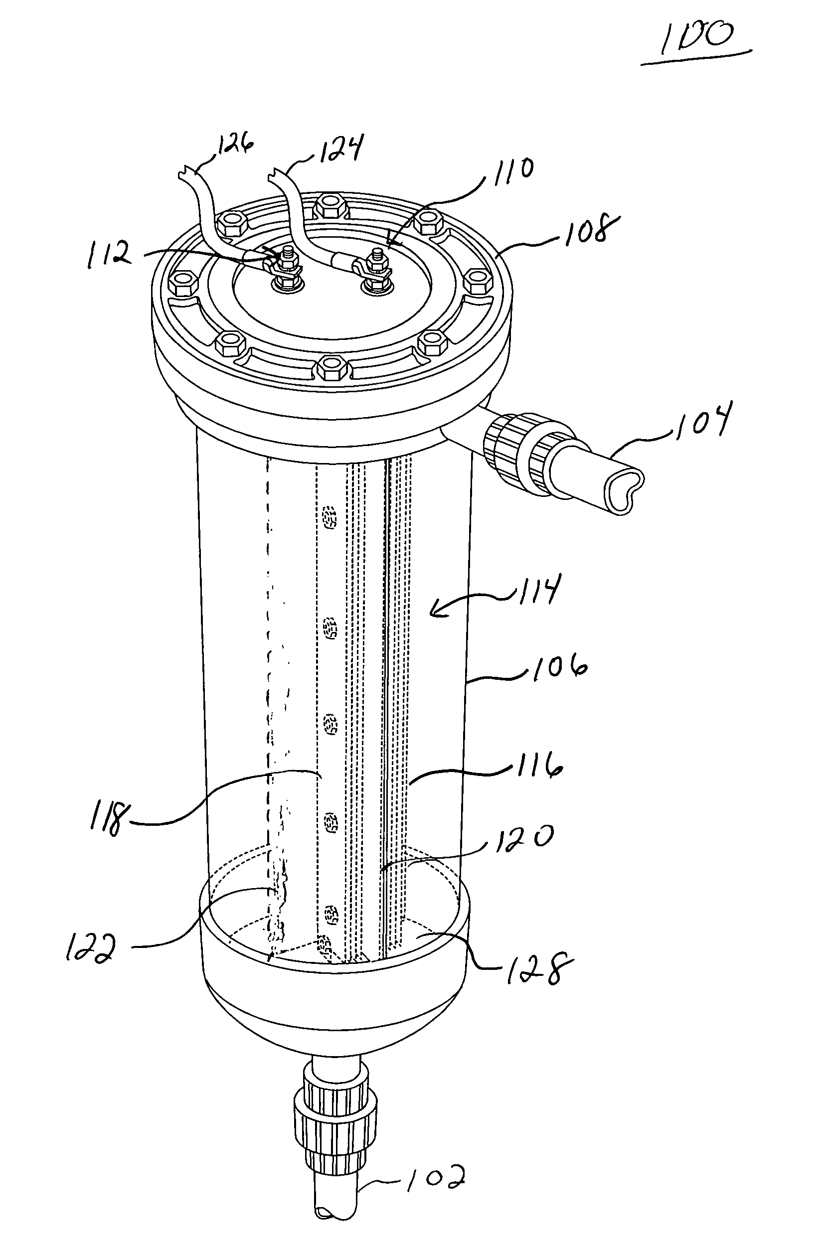
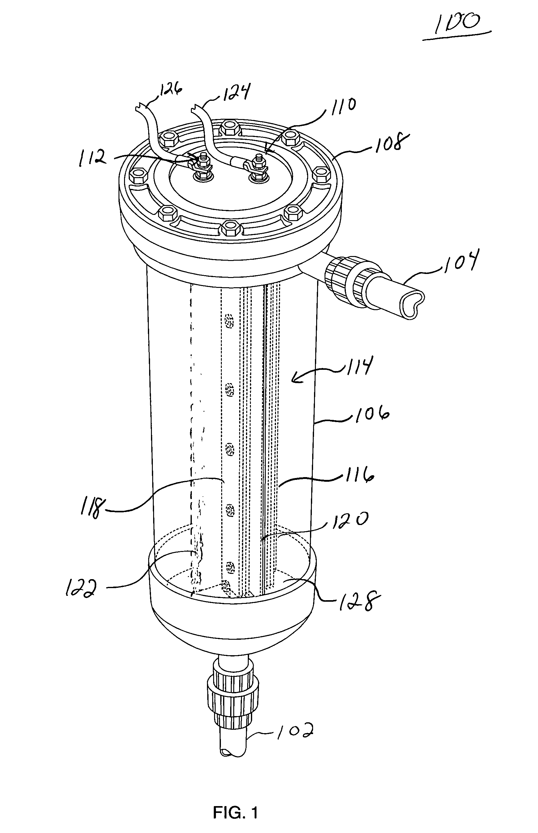
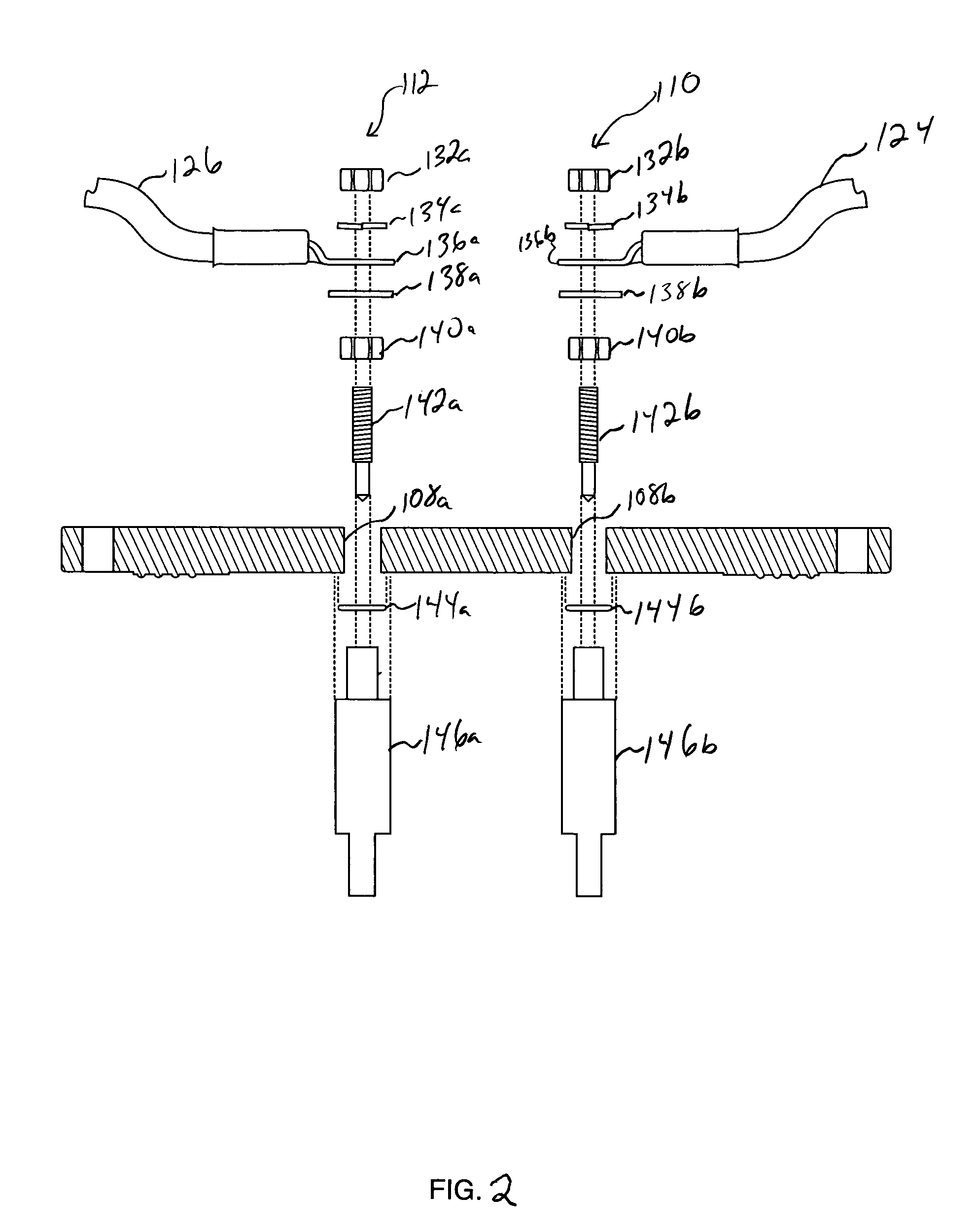
[0055]A particularly advantageous feature of the present invention is the spatial arrangement of the anode and cathode sections, allowing for multiple electrode stacks to be arranged around a common axis. Prior art systems teach a chlorinator having multiple electrode stacks to be arranged in a linear fashion, wherein the addition of electrodes extends the size of the electrode stack along a linear path. Additionally, and in order to accommodate this arrangement of cells around a common axis, another advantageous feature of the present invention are the dividers separating flow between th...


PUM

PropertyMeasurementUnit
voltageaaaaaaaaaa
polarityaaaaaaaaaa
electrical chargeaaaaaaaaaa

Abstract

An improved chlorination system for pools, spas, potable water supplies, and the like, provides a vertically oriented electrolytic cell connected between a pump and a lightly salinated pool. The cell preferably contains a metallic electrode, such as titanium, and a precious metal coated titanium electrode, and has means for passing an electric current through the cell. The present invention further provides a novel electrode stack design, conducive for forming an efficient chlorinator comprising a plurality of interconnecting electrode stacks of separate electrical cells.

Description

CROSS-REFERENCE TO RELATED APPLICATIONS[0001]To the fullest extent permitted by law, the present continuation-in-part application claims priority to and the full benefit of U.S. non-provisional patent application 2005 / 0061662 filed Oct. 18, 2004, U.S. non-provisional patent application Ser. No. 10 / 173,359 filed Jun. 17, 2002 now U.S. Pat. No. 6,821,398, U.S. provisional patent application Ser. No. 60 / 145,537 filed Jul. 26, 1999, U.S. provisional patent application Ser. No. 60 / 148,452 filed Aug. 12, 1999, and U.S. non-provisional patent application Ser. No. 09 / 592,719 filed Jun. 13, 2000, now abandoned.BACKGROUND OF THE INVENTION[0002]1. Technical Field[0003]The present invention relates generally to systems used to chlorinate bodies of water, and more specifically to systems utilizing electrolysis for the electrolytic chlorination of water.[0004]2. Description of Related Art[0005]As is well known, swimming pools, spas, and the like, must be chlorinated to prevent accumulation of alg...

Claims


Application Information

Patent Timeline
Patent Type & Authority Patents(United States)
IPC IPC(8): C02F1/46
CPCC02F1/4674C02F2001/46138C02F2103/42C02F2201/4611C02F2201/4613C02F2201/4617
Inventor VON BROEMBSEN, DAVID
Owner CHLORKING
Learn More