Energy absorbing magnetic coupling device

a magnetic coupling device and energy-absorbing technology, applied in the field of latching mechanisms, can solve the problems of dragging on the rotation and slowing down the door, and achieve the effect of improving the magnetic coupling devi

Inactive Publication Date: 2009-07-28
MACKEN JOHN A
View PDF14 Cites 13 Cited by
  • Summary
  • Abstract
  • Description
  • Claims
  • Application Information

AI Technical Summary

Benefits of technology

[0012]The energy absorbing magnetic coupling device of this invention provides a non-contact magnetic device that exhibits both magnetic braking (energy absorption) and magnetic positioning. One application of this device is a door catch. The device can slow down a closing door, bring the door to a gentle and quiet stop, and then hold the door at a predetermined position.
[0016]It is therefore an object of the present invention to provide a new and improved non-contact device that can gently slow a closing door and quietly bring it to a stop at a predetermined point.

Problems solved by technology

The cavity permits the cylindrical magnet to rotate, but this rotation is impeded by a viscous material that causes a substantial amount of drag on the rotation.
When there is the proper amount of drag, the orientation of the cylindrical magnet results in a magnetic force that opposes relative motion and slows down the door.

Method used


Image

  • Energy absorbing magnetic coupling device
  • Energy absorbing magnetic coupling device
  • Energy absorbing magnetic coupling device

Examples


example 1

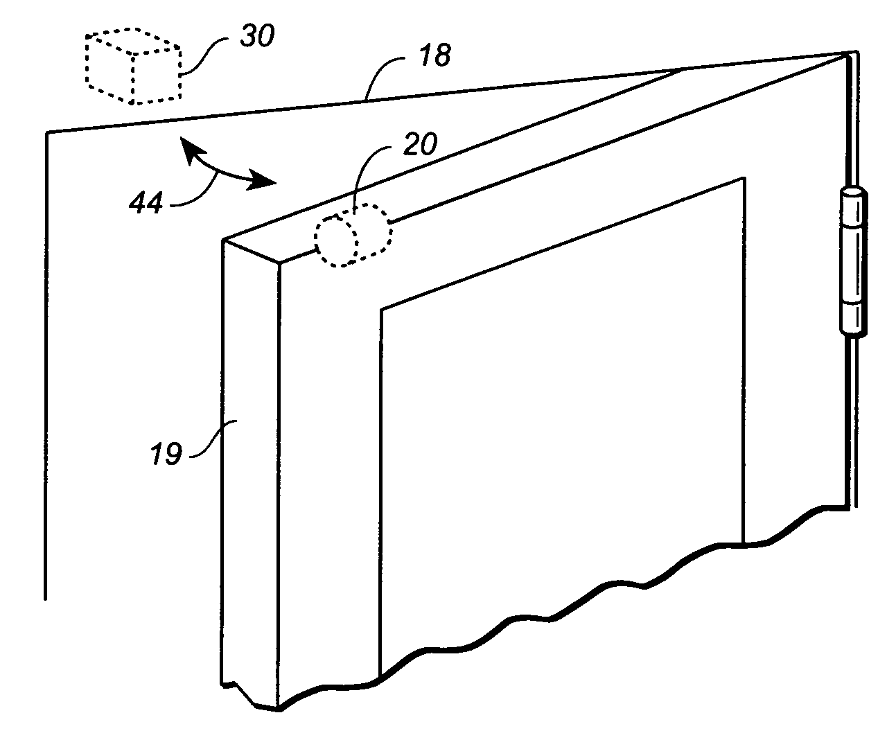
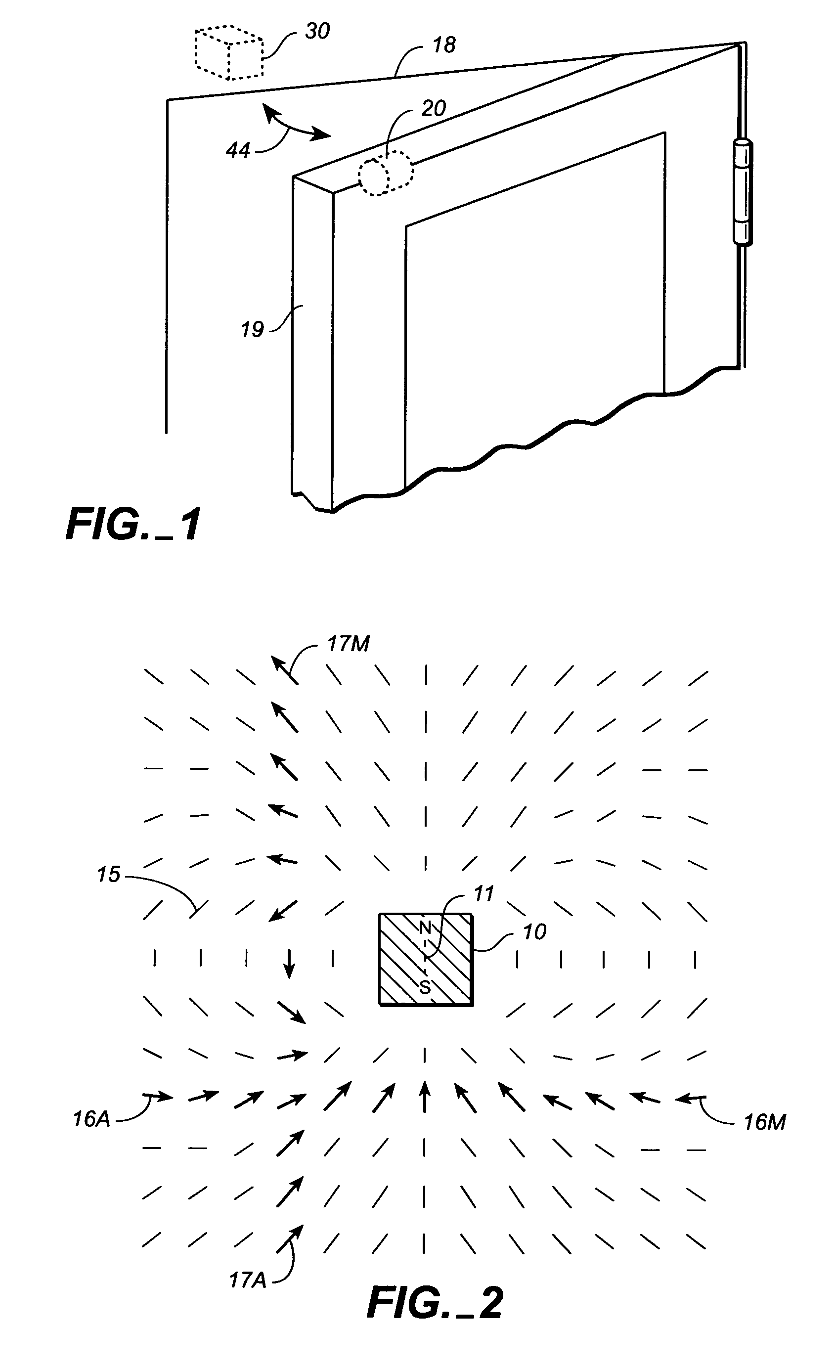
[0072]A successful experiment was performed of a design similar to the preferred embodiment except that a spherical magnet was used rather than a cylindrical magnet. The rotary magnet, reference magnet and bias magnet were all made of the rare earth magnetic material NdFeB. The rotary magnet was a 9.5 mm diameter sphere, the reference magnet was a 9.5 mm cube and the bias magnet was a disk 9.5 mm diameter and 3 mm thick. The bias magnet was removed from the rotary magnet surface by about 7 mm so that the bias magnet produced a much weaker magnetic field than the reference magnet when the reference magnet is at the point of closest approach (about 2 mm from the rotary magnet).

[0073]Mating two hemispherical cavities formed a spherical cavity. Each hemisphere was slightly larger than the 9.5 mm diameter of the spherical magnet. The hemispherical cavities were drilled into 6.3 mm thick aluminum. A first test was performed using axle grease as the viscous material filling a spherical spa...

example 2

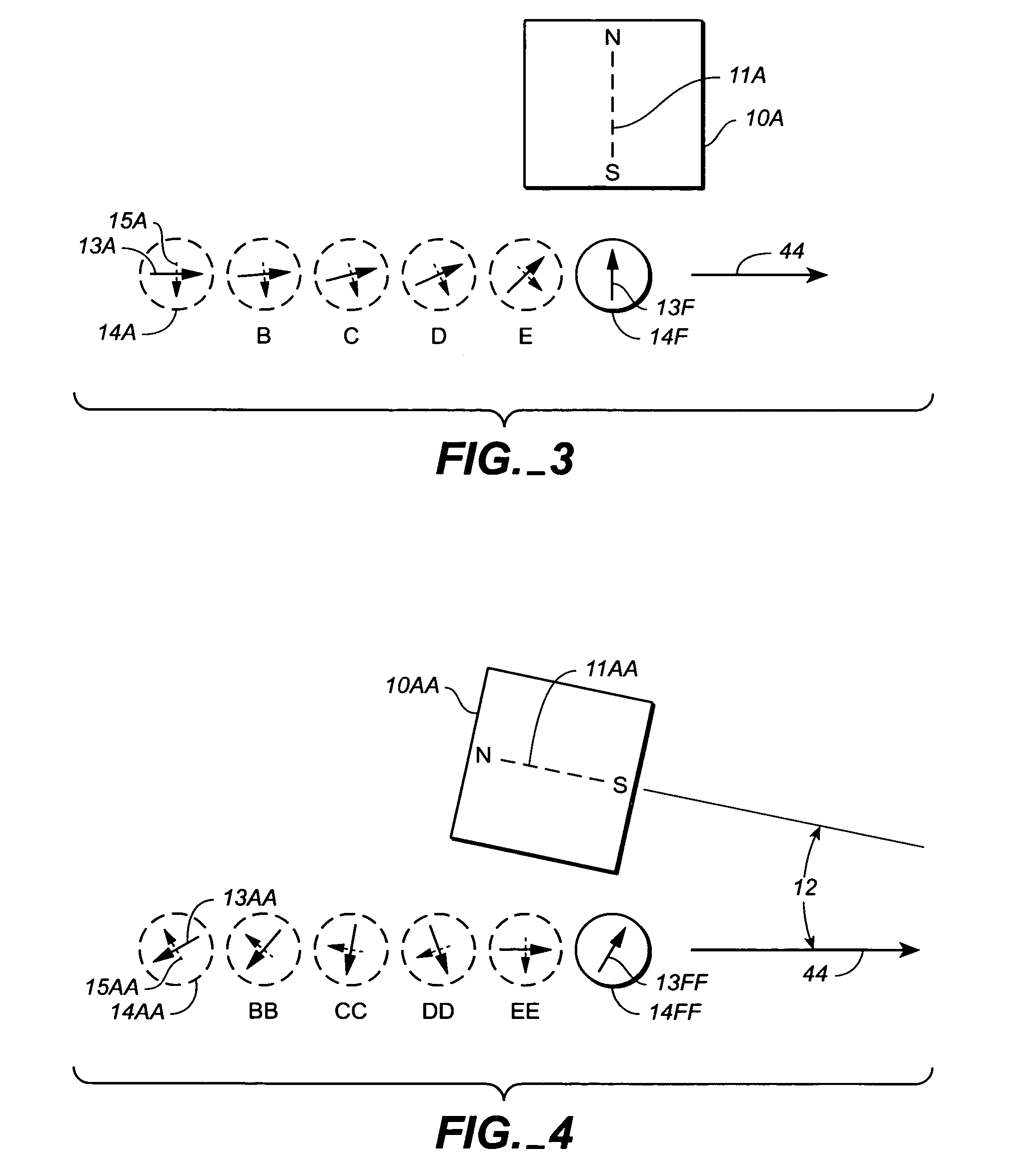
[0076]Thus far, all of the examples had the rotary magnet 20 translate only along a path 44 which does not intersect the reference magnet 30. Another test proved that energy removal could occur even when the reference magnet 30A approached rotary magnet 20A from the direction 47 in FIG. 5. This is the direction parallel to the magnetic axis 31A. The reference magnet would collide with the rotary magnet if it did not first hit a stop. In this experiment, a bias magnet (not shown in FIG. 5) had previously oriented the rotary magnet to an orientation that initially repelled the reference magnet coming from direction 47. Therefore, the initial repulsion removed translational energy when the reference magnet approached. Then the rotary magnet turned 180 degrees inside the housing and the initial repulsion was followed by magnetic attraction. The two magnets were prevented from colliding by a stop. This experiment shows that energy removal can occur with any orientation and translation di...


PUM


Abstract

A non-contact apparatus removes translational energy (slows movement) of a first magnetic assembly when it is moved through the magnetic field of a second magnet. The first magnetic assembly contains a magnet that can rotate, such as a diametrically magnetized cylindrical magnet in a cylindrical cavity. Rotation of the first magnet does work against a predetermined drag. The apparatus also forms a non-contact magnetic coupling that holds a predetermined relative position. The apparatus can be used as a door catch that slows down and quietly stops a door at a predetermined position.

Description

CROSS REFERENCE TO RELATED APPLICATIONS[0001]Not applicable.STATEMENT REGARDING FEDERALLY SPONSORED RESEARCH OR DEVELOPMENT[0002]Not applicable.REFERENCE TO A MICROFICHE APPENDIX[0003]Not applicable.TECHNICAL FIELD[0004]The present invention relates generally to latches and closing mechanisms, and more particularly to an improved magnetic coupling device such as can be used to slow down and quietly stop a door at a predetermined position relative to the doorframe.BACKGROUND INFORMATION AND DISCUSSION OF RELATED ART[0005]Doors to rooms typically have a well known latching mechanism to keep the door closed. To open this latching mechanism, it is necessary to turn a door handle. However, often doors to cabinets or closets do not have a latching mechanism. Instead merely pulling on a door handle typically opens these doors. A different type of mechanism is used to prevent these doors from inadvertently opening. The common name for a device that holds a door closed or open is a a “door c...

Claims


Application Information

Patent Timeline
Patent Type & Authority Patents(United States)
IPC IPC(8): E05C17/56
CPCE05C19/16E05F5/027E05Y2201/21Y10T16/27E05Y2201/266Y10T16/61E05Y2201/254Y10T292/14Y10T292/11
Inventor MACKEN, JOHN A.
Owner MACKEN JOHN A
Why Eureka
Try Eureka