Stretch-forming machine and method

a technology of stretch-forming machine and metal sheet, which is applied in the field of stretch-forming machine, can solve the problems of increasing the possibility of material failure, and achieve the effect of minimizing elongation and minimizing elongation

Active Publication Date: 2009-08-04
CYRIL BATH
View PDF5 Cites 4 Cited by
  • Summary
  • Abstract
  • Description
  • Claims
  • Application Information

AI Technical Summary

Benefits of technology

[0012]It is another object of the invention to provide a method of stretch-forming metal parts that imparts optimum stretch to the edge portions of a stretch-formed part without disturbing the optimum stretch in the center areas of the part.
[0013]These and other objects of the present invention are achieved in the preferred embodiments disclosed below by providing a stretch-forming machine of the type wherein a pair of opposed curving jaw assemblies grip opposite end edge portions of a metal sheet for initially stretching the metal sheet into a yield state and forming the metal sheet into a predetermined curved configuration. Each jaw assembly includes a jaw having an array of adjacent grippers moveable relative to each other to define a part of the curve of the jaw and adapted to extend along one side edge of the metal sheet from adjacent a first corner to adjacent a second corner of the sheet; a moveable yoke connected to the jaw; a pivot connecting the yoke to a beam way; and at least one actuator connected to the yoke for pivoting the jaw about the pivot to urge the grippers at opposing ends of the gripper array away from the pivot while the grippers adjacent a centerline of the gripper array remain approximately stationary. The pivot and the actuator cooperate to stretch the outer corners of the metal sheet while substantially minimizing elongation along the centerline of the metal sheet.
[0019]According to another preferred embodiment of the invention, a stretch-forming machine includes a pair of opposed curving jaw assemblies for gripping opposite end edge portions of a metal sheet, and each jaw assembly includes a jaw having an array of adjacent grippers moveable relative to each other to define a curve in which a center gripper is positioned at an apex of the array intermediate two opposed end grippers of the array, a moveable yoke connected to the jaw, a pivot connecting the yoke to a beam way, and at least one actuator connected to the yoke for pivoting the jaw about the pivot. The axis of the pivot is defined as the intersection of a line tangent to the curve of the array at a point located within the center gripper and a plane defined by the center gripper and the two end grippers. The pivot and the actuator cooperate to stretch the outer corners of the metal sheet while substantially minimizing elongation along the centerline of the metal sheet.
[0020]According to another preferred embodiment of the invention, a method of stretch-forming a metal sheet includes providing a stretch-forming machine of the type wherein a pair of opposed curving jaw assemblies grip opposite end edge portions of a metal sheet to be formed into a predetermined curved configuration, and each jaw assembly includes a jaw having an array of adjacent grippers moveable relative to each other to define a part of the curve of the jaw and adapted to extend along one side edge of the metal sheet from adjacent a first corner to adjacent a second corner of the sheet, a moveable yoke connected to the jaw, a pivot connecting the yoke to a beam way, and at least one actuator connected to the yoke for pivoting the jaw about the pivot. The method further includes stretching the metal sheet to a yield state by retracting the jaws rearwardly away from each other, forming the metal sheet into a desired curvature over a die, and pivoting the jaws about the pivots using the at least one actuator to urge the grippers at opposing ends of the gripper array away from the pivot while the grippers adjacent a centerline of the gripper array remain approximately stationary. The pivot and the actuator cooperate to stretch the outer edges of the metal sheet while substantially minimizing elongation along the centerline of the metal sheet.

Problems solved by technology

Thus, any further stretching of the outer edge portions of the part in an effort to achieve similar elongation of the outer edge portions results in possibly overstretching the longitudinal center portion of the part, thus increasing the possibility of material failure.

Method used


Image

  • Stretch-forming machine and method
  • Stretch-forming machine and method
  • Stretch-forming machine and method

Examples


Embodiment Construction

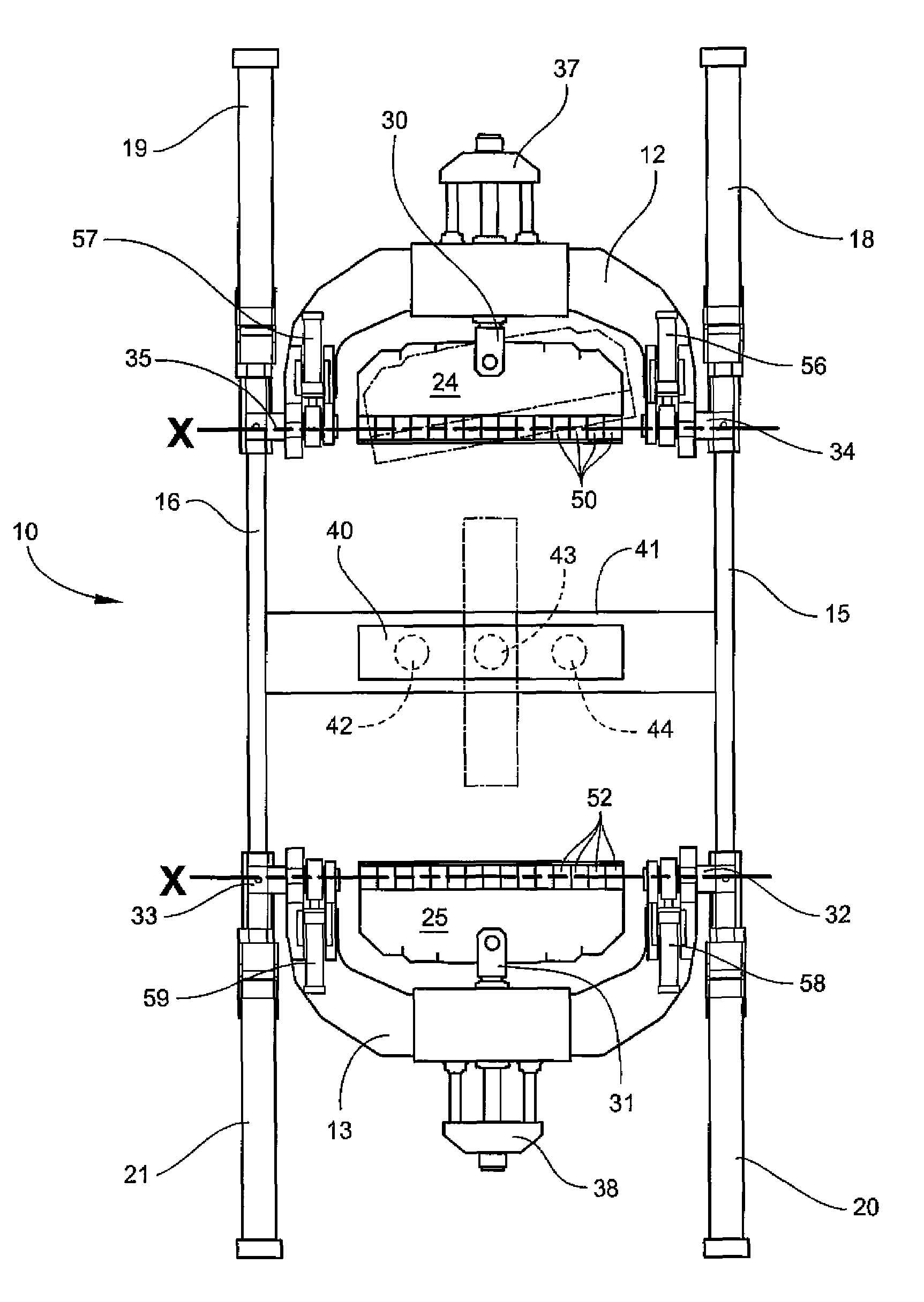
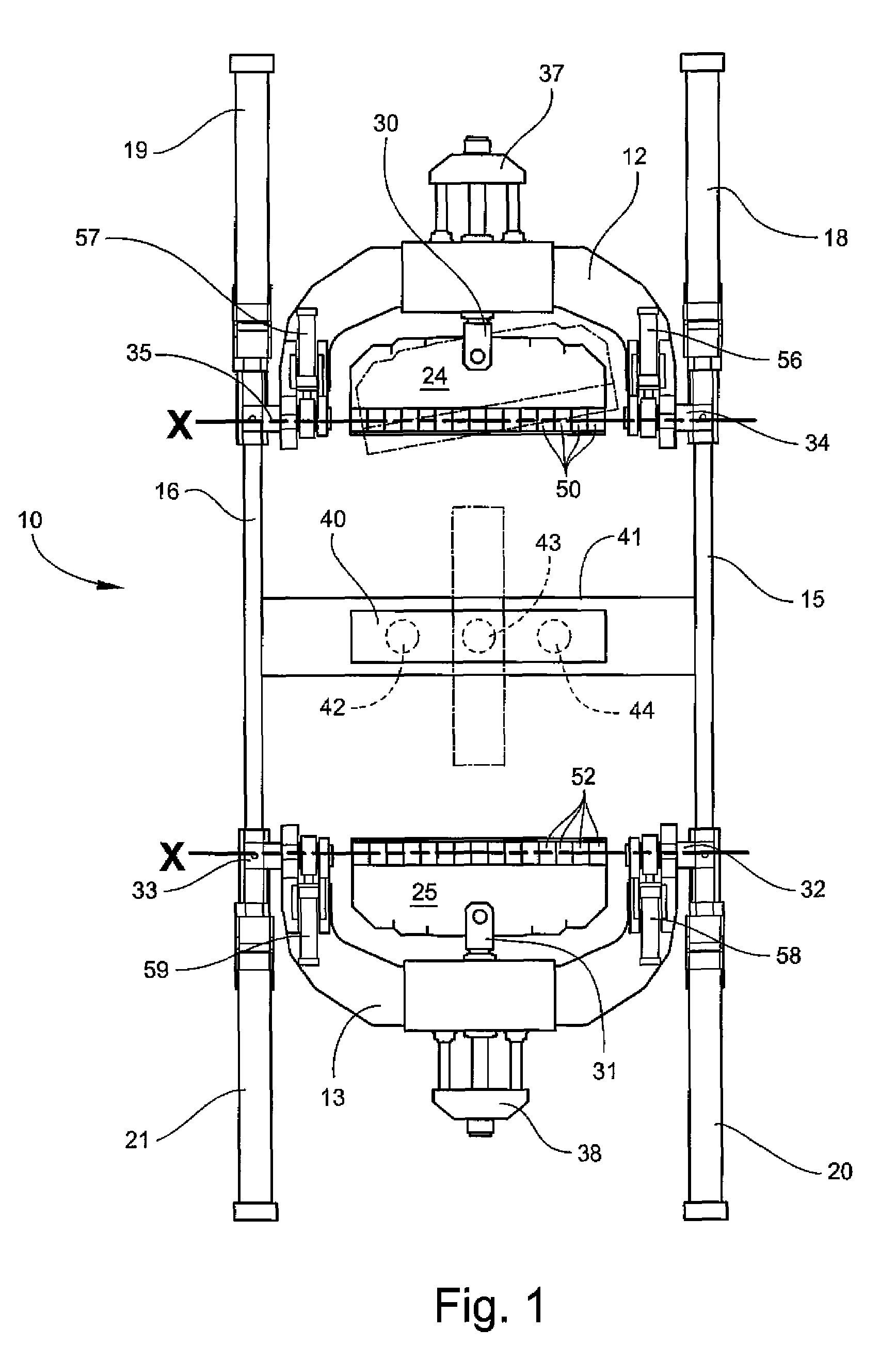
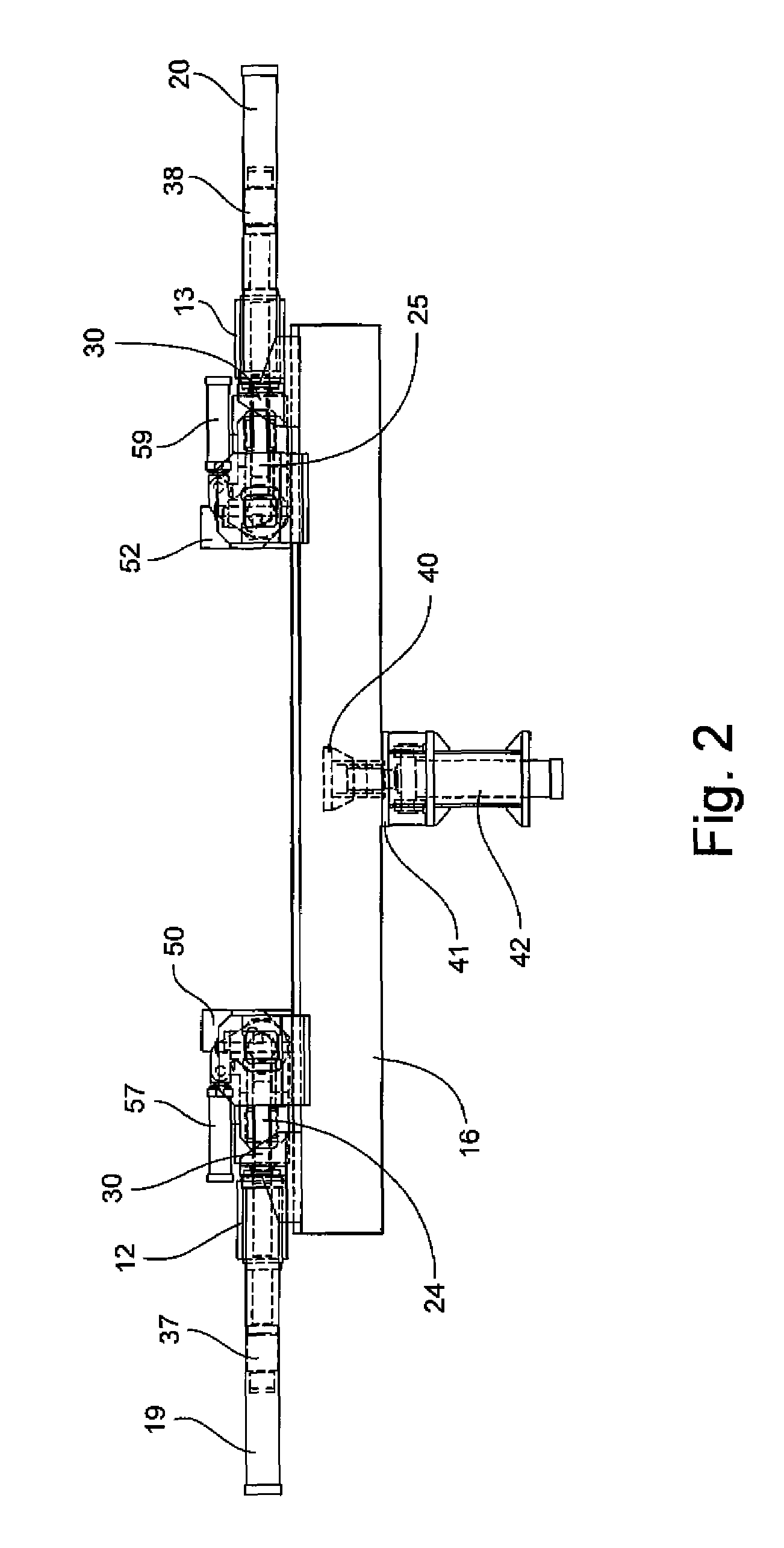
[0038]Referring now specifically to the drawings, a stretch-forming machine 10 according to an embodiment of the invention is shown in simplified form in FIGS. 1 and 2. As generally shown, the stretch-forming machine 10 includes a pair of yokes 12, 13 riding on respective beam ways 15, 16 and actuated by carriage cylinders 18, 19 and 20, 21, respectively. Yokes 12, 13 carry respective jaws 24, 25, each of which are mounted for movement on several axes. Jaw angulation is provided by asymmetric movement of the carriage cylinders 18, 19 (jaw 24) and carriage cylinders 20, 21 (jaw 25).

[0039]Oscillation of jaws 24, 25 is provided by respective pairs of oscillation cylinders, not shown, that are carried on the jaws 24, 25. Jaw rotation is provided by rotation cylinder assemblies through rotation rods 30, 31 that interconnect the yokes 12, 13 and respective jaws 24, 25, and permit the jaws 24, 25 to rotate about a longitudinal horizontal axis relative to the yokes 12, 13 during sheet loadi...


PUM

PropertyMeasurementUnit
areaaaaaaaaaaa
elongationaaaaaaaaaa
shapeaaaaaaaaaa

Abstract

A stretch-forming machine of the type wherein a pair of opposed curving jaw assemblies grip opposite end edge portions of a metal sheet for initially stretching the metal sheet into a yield state and forming the metal sheet into a predetermined curved configuration. Each jaw assembly includes a jaw having an array of adjacent grippers or groups of grippers moveable relative to each other to define a part of the curve of the jaw and adapted to extend along one side edge of the metal sheet from adjacent a first corner to adjacent a second corner of the sheet, a moveable yoke connected to the jaw, a pivot connecting the yoke to a beam way, and at least one actuator connected to the yoke for pivoting the jaw about the pivot to urge the grippers at opposing ends of the gripper array away from the pivot while the grippers adjacent a centerline of the gripper array remain approximately stationary. The pivot and the actuator cooperate to stretch the outer corners of the metal sheet while substantially minimizing elongation along the centerline of the metal sheet.

Description

CROSS-REFERENCE TO RELATED APPLICATIONS[0001]This application claims the benefit of Provisional Application No. 60 / 766,405, Filed Jan. 17, 2006.TECHNICAL FIELD AND BACKGROUND OF THE INVENTION[0002]This invention relates to a metal sheet stretch-forming machine of the type having two opposed clamping jaws. While the term “stretch-forming” is used in this application, the invention is intended to have application to any type of metal-forming machine wherein jaws have a number of adjacent grippers which are collectively curvable so as to closely conform to the shape to be imparted to the metal sheet.[0003]The clamping jaws are formed of a series of hinged grippers that move relative to each other in such a manner as to collectively form concave, convex, or lazy-S curves. These opposed jaws are used to grip opposing ends of a metal sheet while the sheet is stretched into its yield state. While in that state, the metal sheet is formed over a die. Each of the grippers is actuated against ...

Claims


Application Information

Patent Timeline
Patent Type & Authority Patents(United States)
IPC IPC(8): B21D11/02
CPCB21D25/04B21D11/02
Inventor POLEN, LARRY ALEXANDERHARKEY, JONATHAN TODD
Owner CYRIL BATH
Why Eureka
Try Eureka