Cable comprising optical fibres enclosed in an outer sheath

Inactive Publication Date: 2000-04-18
SILEC CABLE
View PDF6 Cites 1 Cited by
  • Summary
  • Abstract
  • Description
  • Claims
  • Application Information

AI Technical Summary

Benefits of technology

Thus, in allowing the cable to bend about an axis parallel to a line interconnecting the two groups of reinforcing members, it is possible to obtain a total cross-section of reinforcing members in which the diameter of each reinforcing member is reduced and, consequently, the thickness of the outer sheath is reduced. The bending capacity of the cable is thus increased.
According to an advantageous aspect of the invention, the number of reinforcing members of each group is selected so that when the cable bends around the minimum radius of curvature of the cable about an axis parallel to a line interconnecting the two groups of reinforcing members, the reinforcing member subjected to the greatest stress is elongated by an amount that is less than the breaking elongation of said reinforcing member. There is thus an optimum compromise between the number of reinforcing members that allow the thickness of the outer sheath to be minimized and the stresses to which the reinforcing members are subjected.

Problems solved by technology

This slows down the rate of production and increases the cost of the cable obtained.
This results in resistance of the cable to bending and in the risk of the reinforcing members breaking if the force applied to the cable is greater than a force which causes the outermost reinforcing members to lengthen to breaking point.
However, in the case of spaced-apart reinforcing members it is not possible to bend the cable about an axis parallel to the line interconnecting the reinforcing members without subjecting the reinforcing members to differential elongation which risks causing them to break.
In both cases the sheath in which the reinforcing members are embedded must itself be relatively thick, thereby reducing the bending capacity and reduces the compactness of the cable.

Method used


Image

  • Cable comprising optical fibres enclosed in an outer sheath

Examples


Embodiment Construction

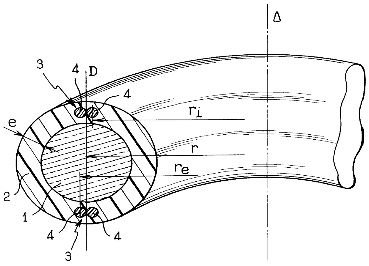
In FIG. 1, the cable of the invention includes a bundle of optical fibers 1, the structure of which is not shown in detail, but which may, for example, be made in the form of one or more groups of optical fibers held together by holding sheaths as described in document FR-A-2 665 266. The bundle of optical fibers is enclosed in an outer sheath 2 having two groups 3 of reinforcing members 4 embedded therein. The groups 3 are diametrally opposite and each comprises two mutually tangential reinforcing members 4 disposed either side of a line D passing via the middle of the bundle of optical fibers. The reinforcing members are made of conventional materials such as metal wires, or strands of glass fiber or aramid, stiffened by a resin having a high traction modulus and a low coefficient of thermal expansion.

By disposing two reinforcing members side by side in each group, it can be seen that for the same total reinforcing member cross-section as would be required using only two diametral...


PUM


Abstract

PCT No. PCT / FR96 / 01088 Sec. 371 Date Jan. 12, 1998 Sec. 102(e) Date Jan. 12, 1998 PCT Filed Jul. 12, 1996 PCT Pub. No. WO97 / 03375 PCT Pub. Date Jan. 30, 1997The cable includes optical fibers (1) enclosed in an outer sheath (2) having elongate reinforcing members (4) embedded therein, disposed in two diametrically opposite groups (3) each comprising a plurality of mutually tangential reinforcing members (4).

Description

The present invention relates to a cable including optical fibers enclosed in an outer sheath.In the cable industry, it is well known that optical fibers must not suffer mechanical stress if both their transmission performance and their lifetime are not to be degraded.To limit traction stresses on optical fibers while cables are being laid, or during temperature variations which cause expansion or retraction of the optical fibers, it is known to use reinforcing members which may be central or peripheral. In the case of a central reinforcing member it is generally necessary to twist the optical fibers or the elements containing the optical fibers. This slows down the rate of production and increases the cost of the cable obtained.To avoid the twisting operation, it is known to make an optical fiber cable by enclosing a bundle of optical fibers in an outer sheath having reinforcing members embedded longitudinally therein. When a cable of this type is subjected to bending, the reinforc...

Claims


Application Information

Patent Timeline
IPC IPC(8): G02B6/44
CPCG02B6/4433G02B6/4432
Inventor JAMET, PATRICK
Owner SILEC CABLE
Why Eureka
Try Eureka