Photosensor control unit for a lighting module

a technology of photosensors and control units, applied in the direction of instruments, semiconductor/solid-state device details, optical radiation measurement, etc., can solve the problems of photo-controls that cannot distinguish between ambient light and light produced by lighting fixtures, photo-controls that are subject to harsh weather, and components of photo-controls to be heated to temperatures

Inactive Publication Date: 2009-08-04
INTENCITY LIGHTING
View PDF22 Cites 87 Cited by
  • Summary
  • Abstract
  • Description
  • Claims
  • Application Information

AI Technical Summary

Benefits of technology

[0011]Aspects of the present invention teach certain benefits in con

Problems solved by technology

Such photocells cannot distinguish between ambient light and light produced by the lighting fixtures.
As a result, the photocells are often positioned in locations where they are subject to harmful conditions.
Sunlight includes destructive ultraviolet radiation, and solar heating causes the components of the photo-controls to be heated to temperatures in excess of 85 degrees Celsius.
In addition, the upper surface mounting of the photo-controls also subjects the photo-controls to harsh weather, debris from trees, and

Method used


Image

  • Photosensor control unit for a lighting module
  • Photosensor control unit for a lighting module
  • Photosensor control unit for a lighting module

Examples


Embodiment Construction

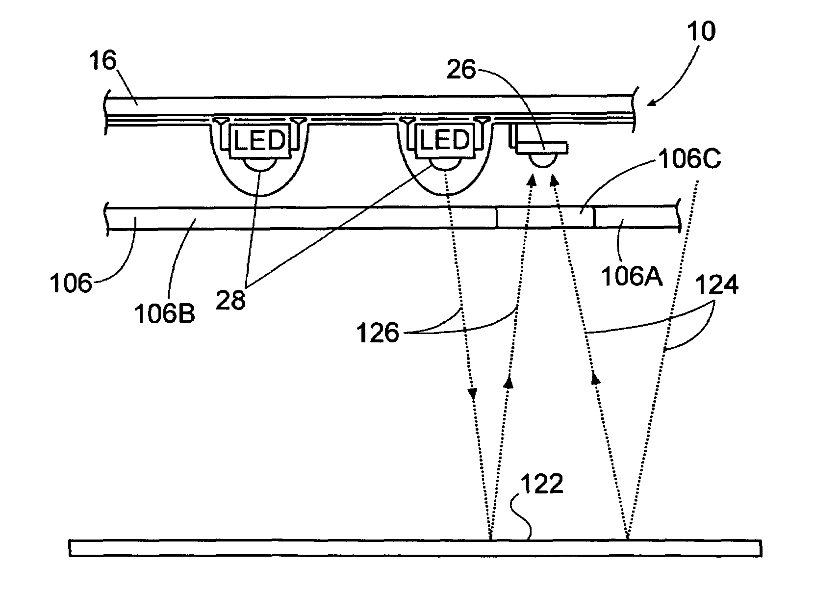
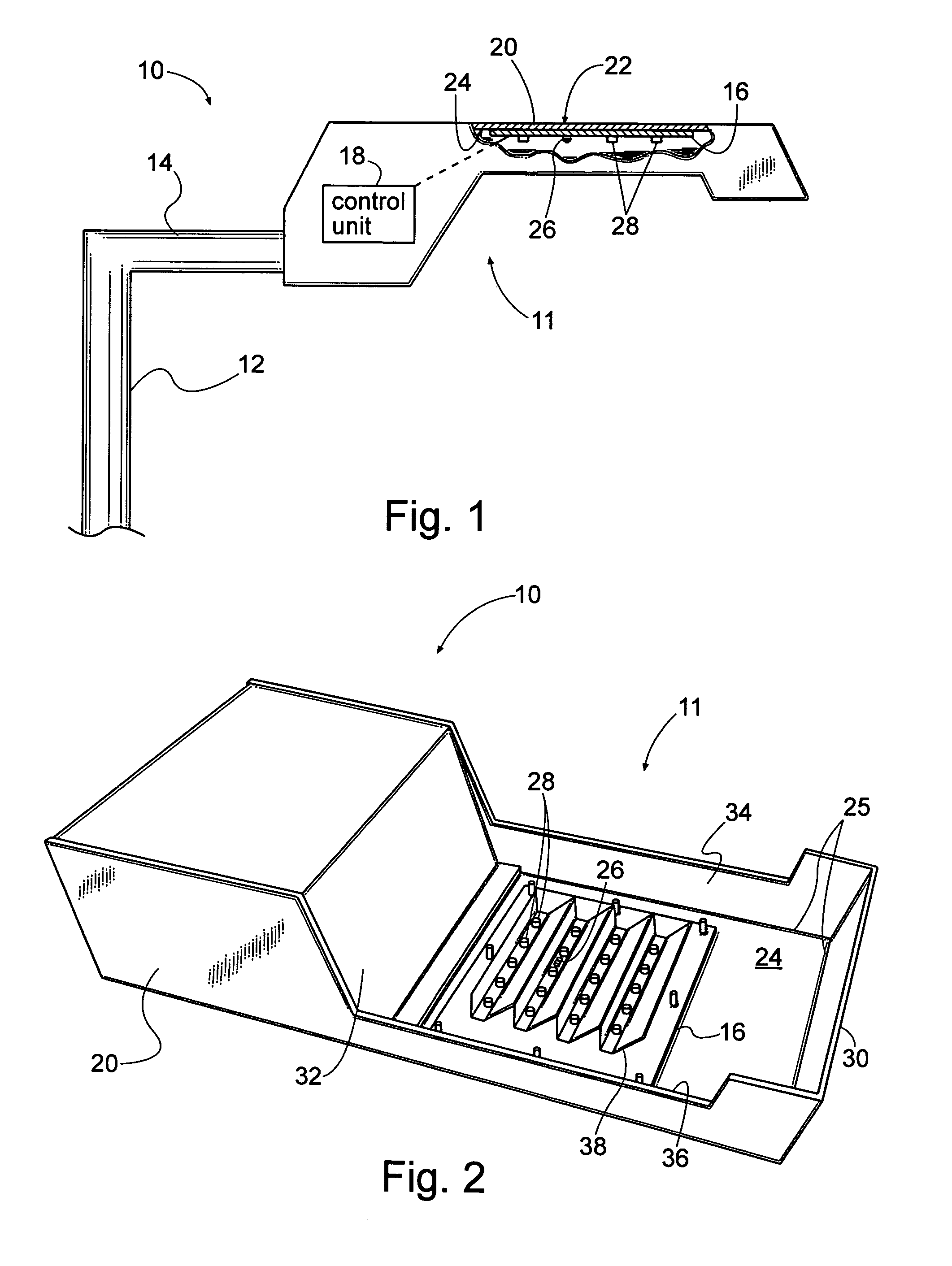
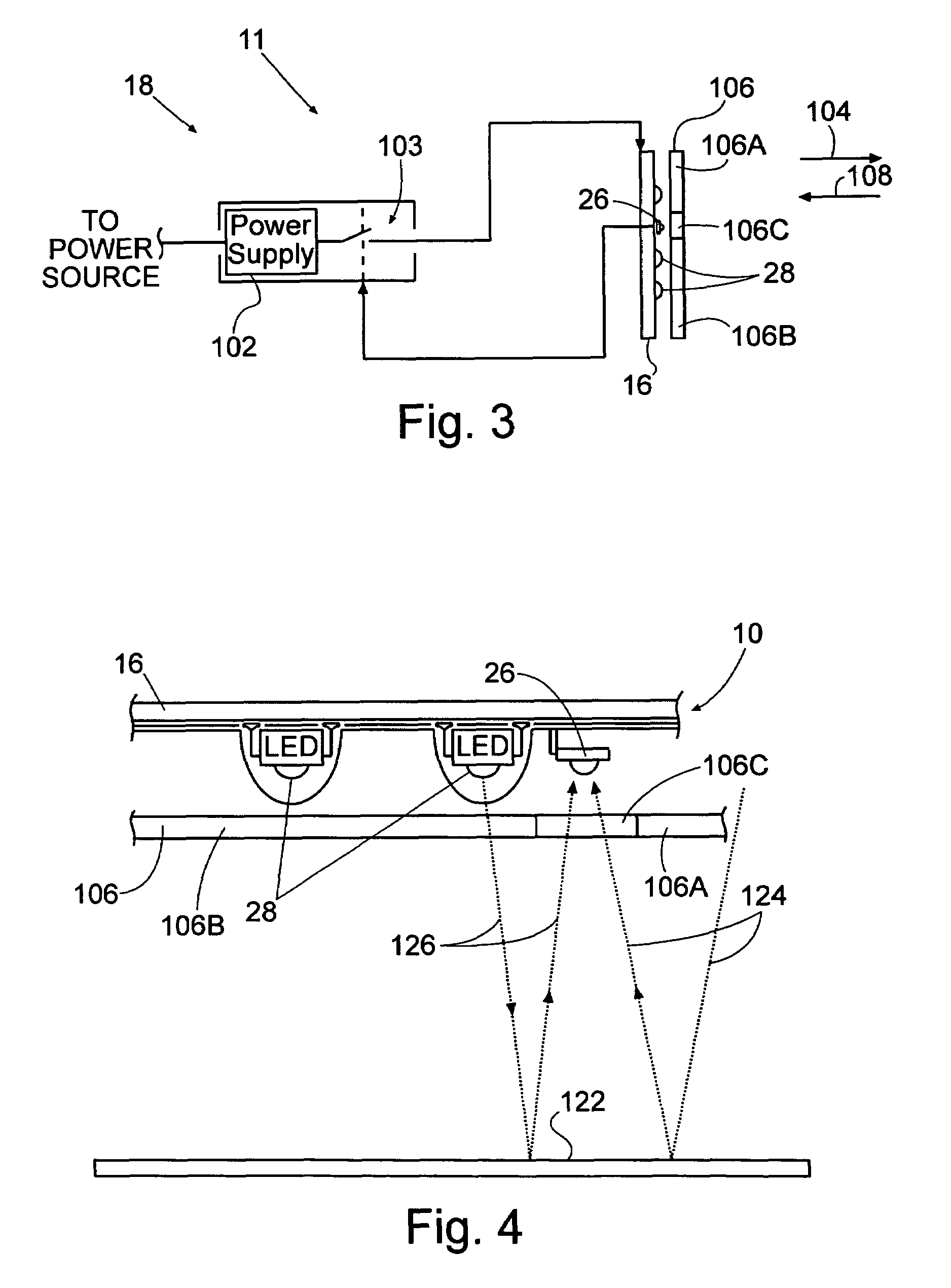
[0026]FIG. 1 is a side elevation view of one embodiment of a lighting module 10 that includes a photosensor control unit 11. In this embodiment, the lighting module 10 is attached to a vertical light pole 12 via a horizontally extending arm 14, and includes a plurality of light-emitting diodes (LEDs) 28 within a protective housing 20. In this embodiment, the housing includes a top surface 22 and an inner surface 24 that extends to a perimeter 25. While LEDs 28 are referred to throughout as the exemplary light source employed in connection with the photosensor control unit 11 of the present invention, those skilled in the art will appreciate that numerous other light sources now known or later developed may be employed without departing from the spirit and scope of the invention. Moreover, as will be apparent from the following description, the photosensor control unit 11 is effectively a stand-alone unit capable of being configured for installation and use on or in conjunction with ...


PUM


Abstract

A photosensor control unit for use in a lighting module has a light sensor and a switch adapted to operably control a light source such as a plurality of LEDs responsive to the light sensor. The light source is adapted to be mounted in the lighting module, and is configured to produce light having wavelengths within a first range of wavelengths. The light sensor is adapted to be mounted on or about the lighting module, and is responsive to light having wavelengths within a second range of wavelengths. The second range of wavelengths is exclusive of the first range of wavelengths. The switch is adapted to operably control the light source responsive to the light sensor such that the light source emits light having wavelengths within the first range of wavelengths responsive to the presence or absence of light within the second range of wavelengths.

Description

RELATED APPLICATIONS[0001]This is a continuation-in-part application of a prior filed application having Ser. No. 10 / 822,537 and a filing date of Apr. 12, 2004 now abandoned.[0002]This application for a utility patent claims the benefit of U.S. Provisional Application No. 60 / 456,111, filed Mar. 20, 2003, and U.S. Utility application Ser. No. 10 / 805,969, filed Mar. 22, 2004. These applications are incorporated herein by reference in their entirety.INCORPORATION BY REFERENCE[0003]Applicant hereby incorporates herein by reference any and all U.S. patents and U.S. patent applications cited or referred to in this application.BACKGROUND OF THE INVENTION[0004]1. Field of the Invention[0005]This invention relates generally to photosensor control units, and more particularly to a photosensor control unit adapted to be used with an outdoor lighting system wherein a light sensor is positioned within the lighting system adjacent a plurality of LEDs or the like of the lighting system.[0006]2. De...

Claims


Application Information

Patent Timeline
IPC IPC(8): G01J1/32H05B37/02
CPCF21V23/0442H05B37/0218F21S8/08F21W2131/10F21W2131/103F21Y2101/02H01L23/3677H01L2924/0002Y02B20/46Y02B20/72H01L2924/00F21Y2115/10H05B47/11Y02B20/40
Inventor MULLINS, PATRICK
Owner INTENCITY LIGHTING
Why Eureka
Try Eureka