Optical fiber

a technology of optical fiber and fiber, applied in the field of optical fiber, can solve the problems of degrading the signal, increasing the scattering intensity, and not enhancing the intensity of the actual transmitted signal, and achieve the effects of low cost, high threshold value, and same mode field diameter (mfd)

Active Publication Date: 2009-08-11
SHIN ETSU CHEM CO LTD
View PDF14 Cites 11 Cited by
  • Summary
  • Abstract
  • Description
  • Claims
  • Application Information

AI Technical Summary

Benefits of technology

[0026]The present invention enables an optical fiber having a high threshold value to cause the SBS to be manufactured at low costs. Furthermore, the optical fiber has approximately the same mode field diameter (MFD) as a normal single mode optical fiber, and therefore suffers from only a small connection loss when connected to a normal single mode optical fiber. Here, the loss spectrum of the optical fiber relating to the present invention is substantially the same as that of a normal low-moisture single mode optical fiber that satisfies the characteristics defined by ITU-T G.652C, even after a hydrogen aging test is conducted on the optical fiber.

Problems solved by technology

The interference between the scattered light and signal light further excites the acoustic phonons, thereby increasing the scattering intensity.
Once the intensity of the signal light reaches a certain level, the increase in the intensity of the signal light input into the optical fiber only raises the scattered light, and does not enhance the intensity of the actually transmitted signal.
On the contrary, such an increase raises noise, thereby degrading the signal.
However, low-cost methods of manufacturing optical fibers based on large preforms have difficulties in varying the parameters in such short intervals, considering that the drawing rate is as high as 1 km / min or higher and, when a large preform is used, a preform having a length of as short as approximately 1.5 mm to 5 mm is sufficient to manufacture an optical fiber of 1 km by drawing.
On the other hand, the method in which thin annular regions are formed so as to be arranged in the radial direction of the optical fiber by using a plurality of dopants is very difficult to be practiced because the dopants disperse in the radial direction during the manufacturing process of the optical fiber.
In addition, an optical fiber manufactured by using this method suffers from a larger loss than a normal optical fiber, and has a small value for Le.
Therefore, this method has difficulties in achieving desired effects.
The optical fiber manufactured by means of this method poses another drawback that an even higher optical energy needs to be input.
Therefore, the effects achieved are insignificant.
Furthermore, the optical fiber has approximately the same mode field diameter (MFD) as a normal single mode optical fiber, and therefore suffers from only a small connection loss when connected to a normal single mode optical fiber.

Method used


Image

  • Optical fiber
  • Optical fiber
  • Optical fiber

Examples


embodiment

First Embodiment

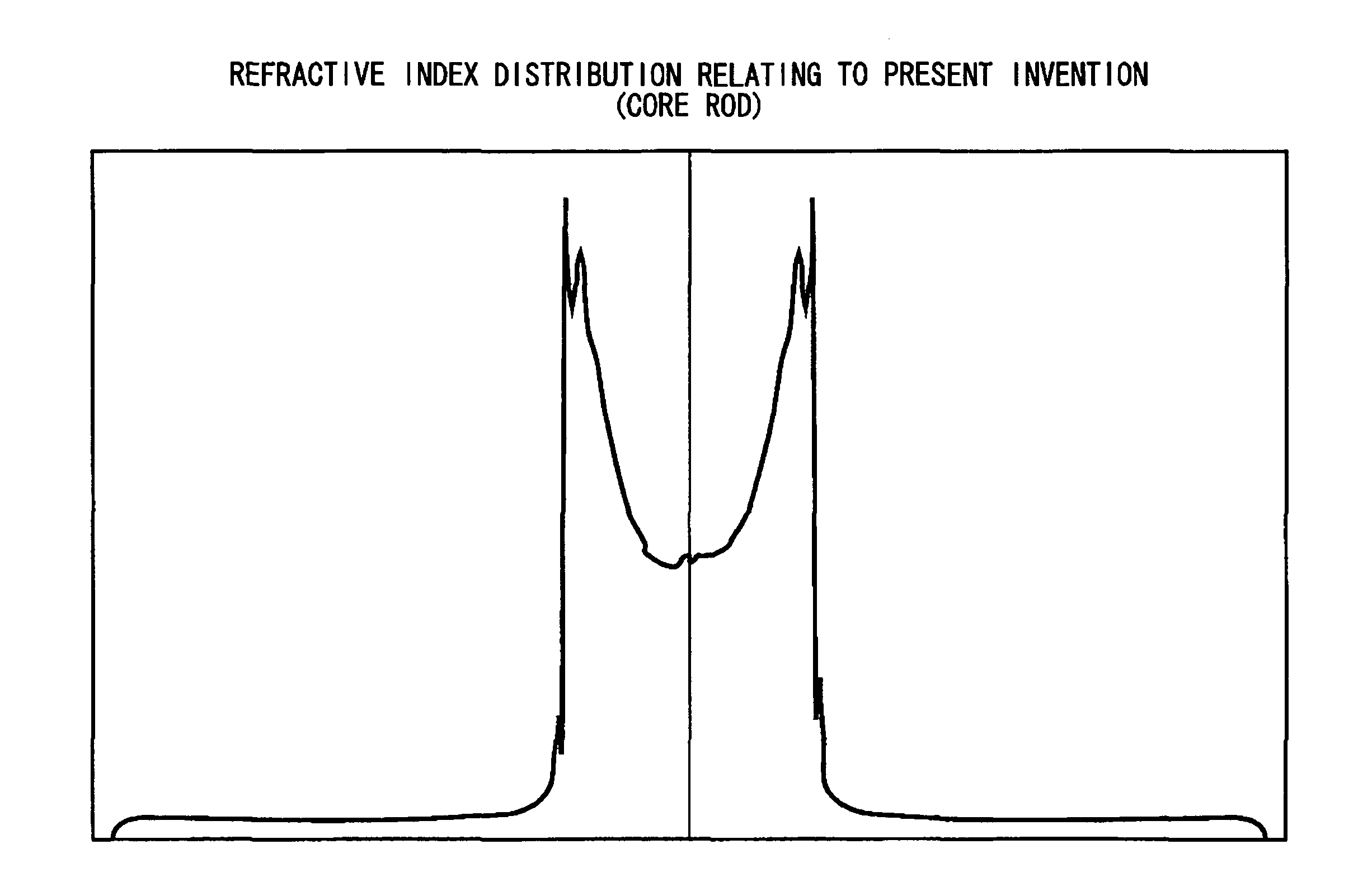
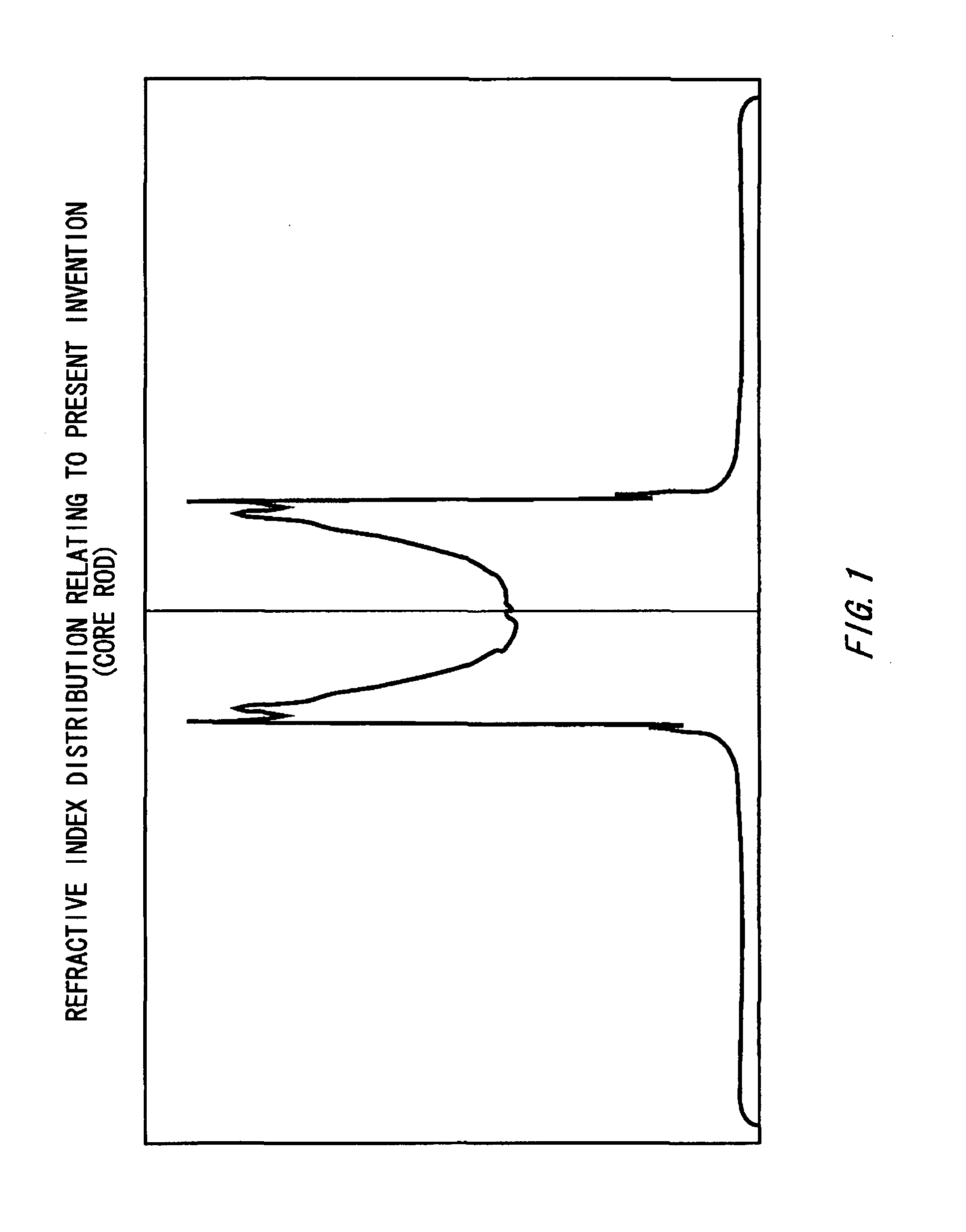
[0039]A core rod including therein a core and a clad is manufactured by means of the vapor phase axial deposition (MAD) method. The manufactured core rod has the refractive index profile shown in FIG. 1. As shown in FIG. 1, the refractive index distribution of the core rod has a unique profile in which the refractive index increases in a substantially continuous manner from the vicinity of the center towards the external surface and symmetrical peaks are formed at positions substantially corresponding to the external periphery of the core. Outside the peaks in the refractive index profile, the refractive index radically drops. Therefore, the portions in the refractive index profile outside the peaks correspond to the clad. Here, when an optical fiber having a diameter of 125 μm is manufactured from the above-mentioned core rod, the core of the manufactured optical fiber has an effective diameter of 8.3 μm.

[0040]The core rod is manufactured by performing deposition wi...


PUM


Abstract

An optical fiber includes a clad portion and a core portion surrounded by the clad portion. Here, the clad portion is formed by substantially pure quartz, and the core portion has a higher refractive index than the clad portion. The optical fiber is characterized in that a relative refractive index difference of a center of the core portion falls within a range from 0.15% to 0.30%, and a maximum relative refractive index difference of the core portion falls within a range from 0.4% to 0.6%. Here, it is preferable that an average relative refractive index difference of the core portion falls within a range from 0.30% to 0.40%. Here, a mode field diameter of the optical fiber falls within a range from 8.6 μm to 9.5 μm at 1310 nm, and a cable cutoff wavelength of the optical fiber is equal to or lower than 1260 nm. Note that, after the optical fiber is subjected to hydrogen aging, a loss of the optical fiber is preferably equal to or lower than 0.4 dB / km at 1383 nm.

Description

CROSS REFERENCE TO RELATED APPLICATION[0001]This is a continuation application of PCT / JP2005 / 019314 filed on Oct. 20, 2005 which claims priority from Japanese Patent Applications No. 2004-316796 filed on Oct. 29, 2004 and No. 2005-048792 filed on Feb. 24, 2005, the contents of which are incorporated herein by reference.BACKGROUND[0002]1. Technical Field[0003]The present invention relates to an optical fiber for use in the field of optical communication applications which input, into the optical fiber, signal light having a relatively high optical energy.[0004]2. Related Art[0005]According to applications such as passive optical network (PON) systems, signals are transmitted via a single optical fiber to a location near subscribers and split at the location appropriately in accordance with the number of the subscribers. When this technique is utilized, the further the splitting location is positioned from the base station, or the larger the number of the subscribers is, the higher op...

Claims


Application Information

Patent Timeline
Patent Type & Authority Patents(United States)
IPC IPC(8): G02B6/02
CPCG02B6/03611G02B6/02004G02B6/0281G02B6/02019G02B6/028
Inventor INOUE, DAIOYAMADA, HIROSHIMORISHITA, YUICHI
Owner SHIN ETSU CHEM CO LTD
Why Eureka
Try Eureka