Supercharge Your Innovation With Domain-Expert AI Agents!

Threaded coupling with flow shutoff

a technology of flow shutoff and threaded coupling, which is applied in the direction of water supply installation, couplings, transportation and packaging, etc., can solve the problems of prior art devices not including, leakage from the female coupling half, and the tubular body shutoff is not desirable, so as to prevent the disconnection (uncoupling) of the coupling

Inactive Publication Date: 2009-08-18
SNAP TITE TECH
View PDF349 Cites 28 Cited by
  • Summary
  • Abstract
  • Description
  • Claims
  • Application Information

AI Technical Summary

Benefits of technology

"The patent describes a coupling for joining two parts together. The coupling includes a male half and a female half, each with a valve and a sliding sleeve. The sliding sleeves have detents that engage with the valves to secure the parts together. The valves have a recess that the detents lock into, and the sliding sleeves have a shoulder that engages a locking ring to secure the parts in a locked position. The female half also has a recess that the detents lock into. The coupling is designed to easily connect and disconnect the parts, and it has a protective cover to prevent damage to the valves when not in use. The technical effect of this design is to provide a reliable and easy-to-use coupling for joining two parts together."

Problems solved by technology

Floating of the tubular body shutoff is not desirable because it promotes incomplete closure of the tubular body shutoff against the valve or bolt 5.
If the tubular shutoff body 7 of the '141 patent does not move fully outwardly due to swelling of the seals in the device or because of tight tolerances between the parts and uneven expansion thereof, then the tubular shutoff body fails to close thus creating a leak from the female coupling half.
However, the design of the prior art device does not include an interlock of the tubular body shutoff with the male coupling half to insure its closure.

Method used


Image

  • Threaded coupling with flow shutoff
  • Threaded coupling with flow shutoff
  • Threaded coupling with flow shutoff

Examples


Embodiment Construction

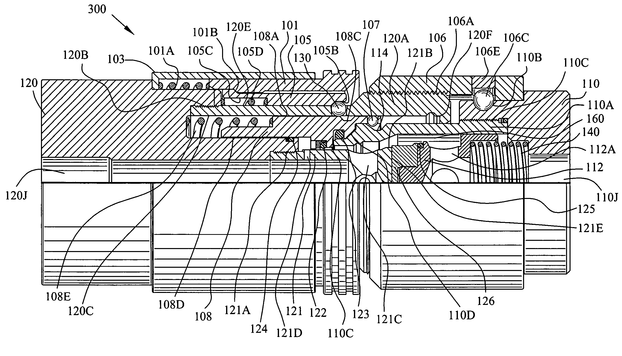
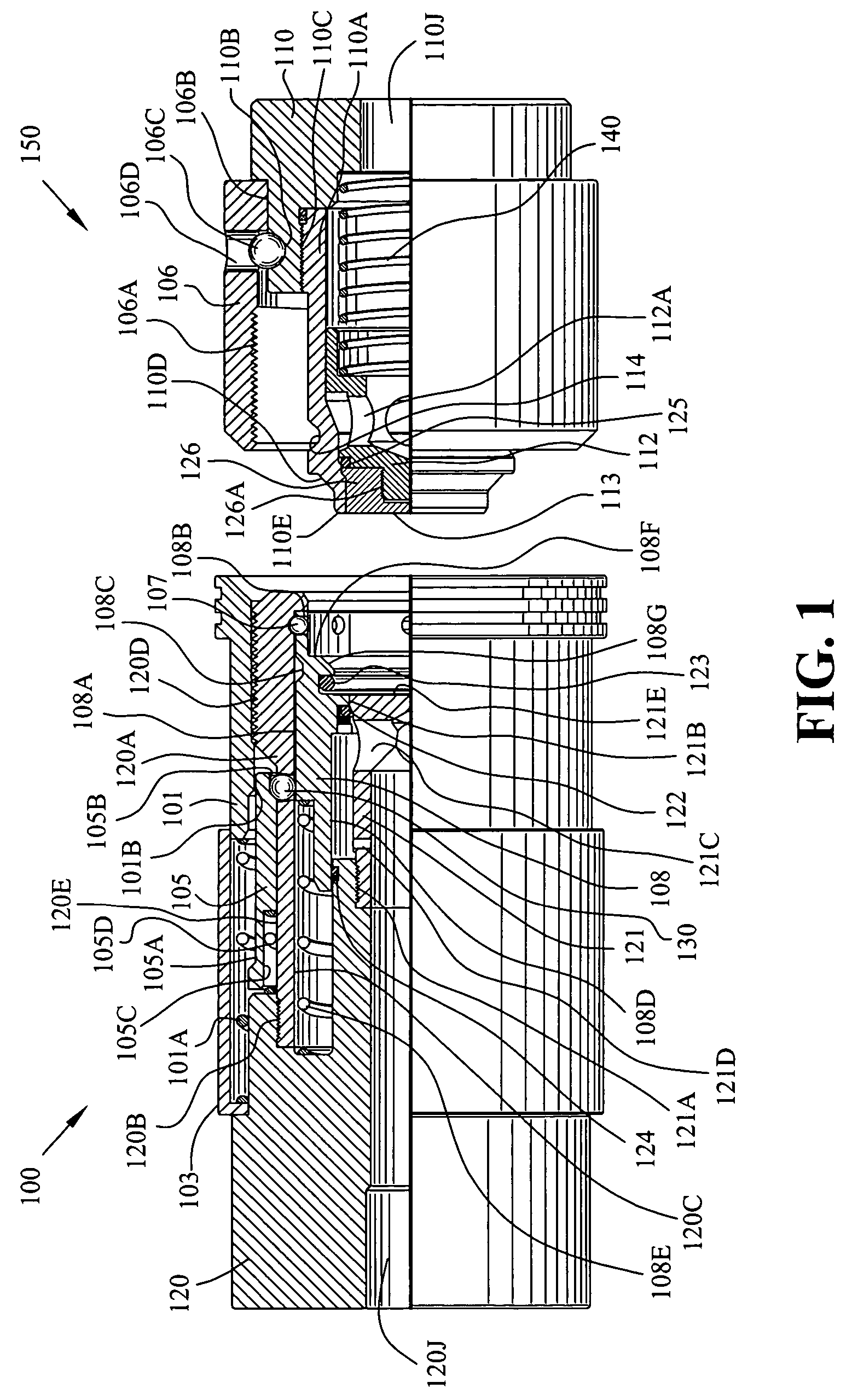
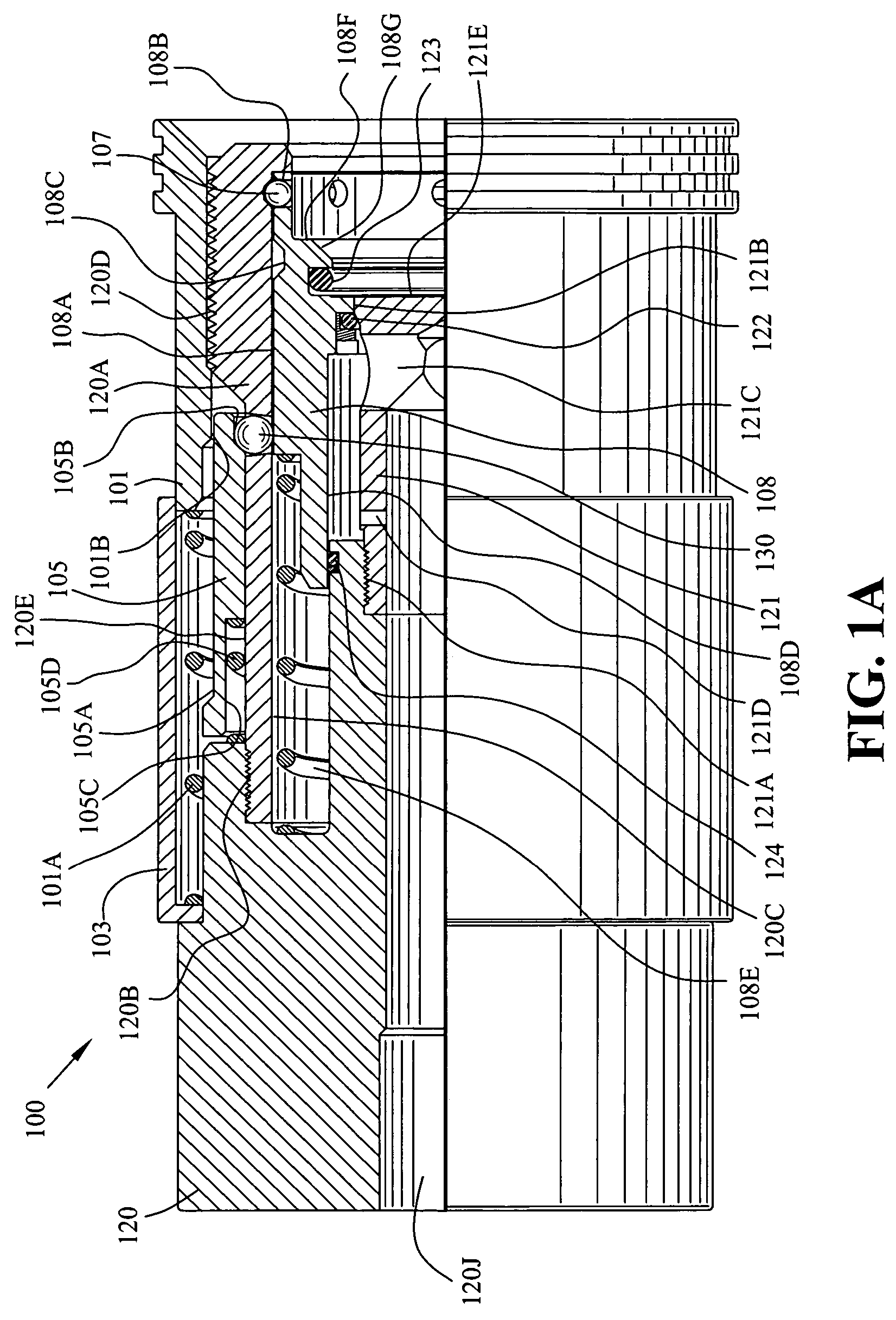
[0034]FIG. 1 is a quarter-sectional view of the female coupling half 100 and the male coupling half 150 uncoupled. FIG. 1A is an enlarged quarter-sectional view 100 of the female coupling half of FIG. 1. And, FIG. 1B is an enlarged quarter-sectional view 150 of the male coupling half of FIG. 1.

[0035]Referring to FIGS. 1, 1A and 1B, female coupling half 100 includes a body 120 and a body extension 120A threaded 120B thereto. Body extension 120A is essentially concentric with respect to body 120. A passageway 120J is centrally located in body 120. The materials of the body 120 and other structural parts can be any material capable of handling hydraulic fluid at high pressure such as, for instance, stainless steel. The seals used herein may be any suitable elastomeric material used in high pressure hydraulic fluid applications. Body extension 120A includes an inner surface 120C and an outer surface 120E. A portion of the outer surface of the body extension 120A includes threads 120D. T...


PUM


Abstract

A thread to connect coupling comprising a female coupling half and a male coupling half is disclosed and claimed wherein the male coupling half includes a recess in the exterior of the male body which extends circumferentially therearound. The female coupling half includes a valve, a female body, and a female body extension affixed to the female body. The female body further includes a sliding sleeve movable with respect to the valve between a first position abutting and closing the valve and a second position opening the valve. The male body interengages the sliding sleeve and moves therewith during coupling and uncoupling. During uncoupling, the sliding sleeve is reliably positioned sealingly against the valve because the sliding sleeve is interlocked with the male body such that as the male body is withdrawn from the female body the sliding sleeve comes with the male body. Separation of the coupling halves requires that an outer sleeve release a second set of detents which acts as a permissive to uncoupling. The coupling halves may not be separated by vibrating the threaded surfaces of the respective coupling halves apart.

Description

FIELD OF THE INVENTION[0001]The invention is in the field of flush face couplings which are threaded together under pressure applied to both the male coupling half and the female coupling half. The coupling of the invention may be used in construction, agriculture and in various manufacturing processes.BACKGROUND OF THE INVENTION[0002]U.S. Pat. No. 5,662,141 to Arosio issued Sep. 2, 1997 discloses a leak resistant fluid coupling arrangement whereby the female coupling half includes a tubular body shutoff upon which a male body and seal sit. See, FIG. 5 labeled “prior art” herein which is substantially similar to FIG. 3 of the '141 patent illustrating the male body 40 and seal 17′' residing adjacent and in engagement with the tubular body shutoff 7 of the female coupling half 2. FIG. 5 is a cross-sectional view 500 of a prior art female coupling half 2 and male coupling half 3 coupled. Reference numeral 4 indicates a hole or passageway for the communication of fluid therethrough. Ref...

Claims


Application Information

Patent Timeline
Patent Type & Authority Patents(United States)
IPC IPC(8): F16L37/23
CPCF16L29/04Y10T137/87965Y10T137/87949
Inventor ZEIBER, DENNISWILKINS, STEVE
Owner SNAP TITE TECH
Features
  • R&D
  • Intellectual Property
  • Life Sciences
  • Materials
  • Tech Scout
  • Unparalleled Data Quality
  • Higher Quality Content
  • 60% Fewer Hallucinations
Learn More