

Lever connect PTO module for three-point hitch quick coupler
a technology of pto module and latch, which is applied in the direction of interengaging clutches, couplings, agricultural machines, etc., can solve the problems of reducing the benefits of quick attaching couplers, time-consuming, dirty, and often difficult for operators to perform the task
- Summary
- Abstract
- Description
- Claims
- Application Information
AI Technical Summary
Benefits of technology
Problems solved by technology
Method used
Image

Examples
Embodiment Construction
)
[0024]Many of the fastening, connection, processes and other means and components utilized in this invention are widely known and used in the field of the invention described, and their exact nature or type is not necessary for an understanding and use of the invention by a person skilled in the art, and they will not therefore be discussed in significant detail. Also, any reference herein to the terms “left” or “right” are used as a matter of mere convenience and are determined by standing at the rear of the machine facing in its normal direction of travel. Furthermore, the various components shown or described herein for any specific application of this invention can be varied or altered as anticipated by this invention and the practice of a specific application of any element may already by widely known or used in the art by persons skilled in the art and each will likewise not therefore be discussed in significant detail.
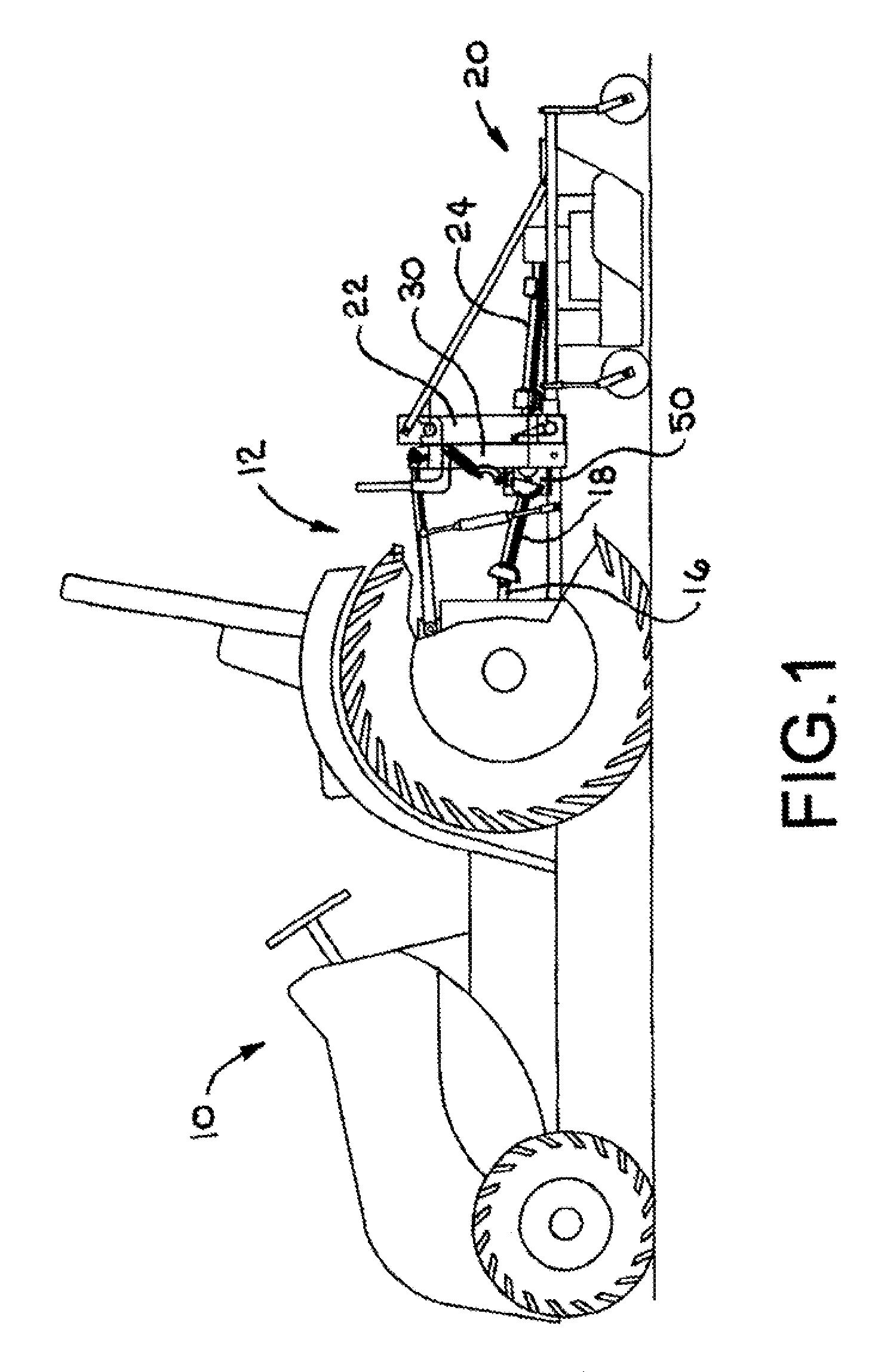
[0025]Referring to FIG. 1, tractor 10 is shown having thr...
PUM
 Abstract
Description
Claims
Application Information