Immersion nozzle for continuous casting of steel and method of continuous casting method of steel

a technology of continuous casting and immersion nozzle, which is applied in the direction of molten metal supply equipment, melt-holding vessels, manufacturing tools, etc., can solve the problems of difficulty in completely removing alsub>2, blocking of immersion nozzle, and various problems relating to casting operations and quality of cast steel strands

Inactive Publication Date: 2009-08-18
JFE STEEL CORP
View PDF18 Cites 0 Cited by
  • Summary
  • Abstract
  • Description
  • Claims
  • Application Information

AI Technical Summary

Benefits of technology

[0015]It is an object of the present invention to provide an immersion nozzle for steel continuous casting and a method for continuous casting of steel, in which, in steel continuous casting, the immersion nozzle can prevent blocking caused by Al2O3 contained in molten steel without degrading the stability of continuous casting operation and the purity of cast steel strands.

Problems solved by technology

Al2O3 particles formed in this deoxidation step are removed from the molten steel by floatation separation using the difference in density between molten steel and Al2O3; however, since the floating speed of fine Al2O3 particles having a size of several tens of micrometers or less is extremely slow, it has been very difficult to totally remove Al2O3 by the floatation separation in a practical process.
However, in the case in which Al2O3-graphite base or Al2O3—SiO2-graphite base immersion nozzles are used, when flowing through an immersion nozzle made of Al2O3-graphite base or Al2O3—SiO2-graphite base material, Al2O3 suspended in molten steel is deposited and accumulated on an inner wall of the immersion nozzle, and as a result, blocking of the immersion nozzle occurs.
When the immersion nozzle is blocked, various problems relating to casting operations and qualities of cast steel strands occur.
For example, a drawing speed of cast steel strand must be inevitably decreased, resulting in decrease in productivity, and in an extreme case, casting operation is forced to stop.
In addition, when Al2O3 deposited on an inner wall of the immersion nozzle is suddenly peeled away to form large Al2O3 particles, is discharged into a mold, and is then trapped in a solidification shell in the mold, defects of products occur.
Furthermore, due to delay of solidification at this part, molten steel may flow out in some cases when a cast steel strand is drawn out under the mold, and as a result, even breakout may occur in some cases.
However, the measures described above have the following problems.
In pores (pinholes) generated by the trapped Ar gas, inclusions are also observed in many cases, resulting in defects of products.
In addition, when part of the Ar gas is trapped at a surface portion of a cast steel strand, the interior surfaces of the pores are oxidized in a continuous casting machine or a heating furnace before rolling, and those mentioned above are not scaled off in some cases, resulting in defects of products.
However, according to this method, since being turned into the liquid form, the inclusions are difficult to be separated from the molten steel and are poured into a mold together therewith, and as a result, a cast steel strand containing a large amount of inclusions is formed.
Hence, there has been a problem in that the purity is degraded.
The reason for this is that a refractory has a low heat shock resistance and is liable to be cracked.
However, since the low melting point compound which forms inclusions is poured into the mold, there has been a problem in that the purity of a cast steel strand is degraded.
In addition, since the inner wall of the immersion nozzle is worn away, this method cannot be suitably used for casting which lasts for a long period of time.
As has thus been described above, the conventional measures for preventing Al2O3 deposition can prevent the immersion nozzle from being blocked; however, for example, the amount of inclusions in a cast steel strand may be increased and the stability of operation may be interfered with in some cases.
Hence, the measures of preventing Al2O3 deposition, which can meet all the requirements in view of the operation and the quality of cast steel strands, have not been established as of today.

Method used


Image

  • Immersion nozzle for continuous casting of steel and method of continuous casting method of steel
  • Immersion nozzle for continuous casting of steel and method of continuous casting method of steel
  • Immersion nozzle for continuous casting of steel and method of continuous casting method of steel

Examples


example 1

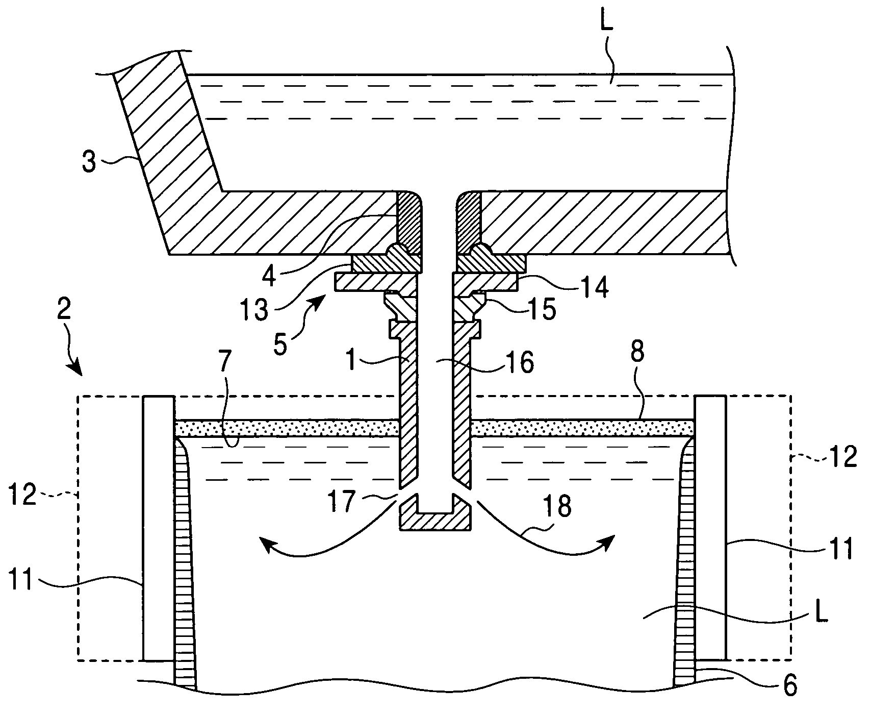
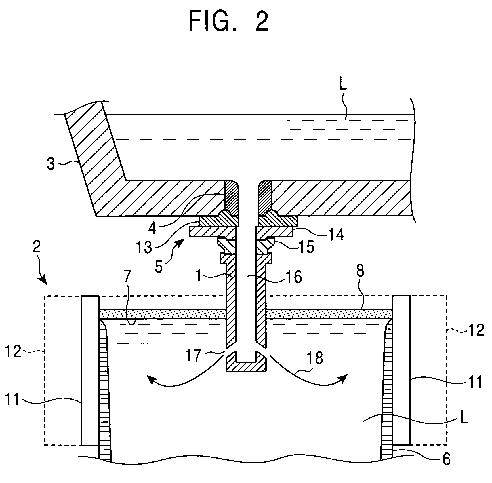
[0106]At least one metal selected from the group consisting of Al, Ti, Zr, Ce, and Ca, which was a component of reducing MgO, was compounded with a refractory material including an oxide containing MgO, thereby forming various refractory compositions indicated by Nos. 1 to 19 shown in Table 1. The refractory compositions thus formed were each used as the refractory 22 shown in FIG. 3 or 4, and were formed into immersion nozzles having the shapes shown in FIG. 3 or 4. By using the immersion nozzles thus formed, continuous casting of molten steel was performed using the continuous casting machine shown in FIG. 2. In the case of the insertion type immersion nozzle shown in FIG. 4, an Al2O3-graphite base refractory was used as a mother refractory which was provided around the outside periphery of the immersion nozzle. In addition, for purposes of comparison, casting was also performed using an immersion nozzle made of a conventional Al2O3-graphite base refractory indicated by Nos. 20 an...

example 2

[0111]As shown in Table 2, No. 22 having the same composition as that of No. 1 shown in Table 1 was regarded as a basic composition, and by using refractories having compositions of Nos. 23 to 26, each having the basic composition described above and CaO contained therein, as the refractory 22 shown in FIG. 4, the insertion type immersion nozzle shown in FIG. 4 was formed. Subsequently, by using this immersion nozzle, molten steel was processed by continuous casting using the continuous casting machine shown in FIG. 2.

[0112]After 8 heats, in which 300 ton was per one heat, were continuously processed by casting, the immersion nozzle used in this process was recovered, and deposits on the inner wall right above the discharge hole and the state of the immersion nozzle were observed. The type of cast steel was low-carbon aluminum-killed steel (C: 0.04 to 0.05 mass percent, Si: trace, Mn: 0.1 to 0.2 mass percent, and Al: 0.03 to 0.04 mass percent), and the slab width was in the range of...

example 3

[0116]A continuous casting machine (two-strand type machine) having the mold portion as shown in FIG. 2 was used, and for one strand, the immersion nozzle of the present invention was used. That is, in the immersion nozzle mentioned above, as shown in FIG. 7, a refractory composed of an MgO-carbon-Al metal base material containing Al2O3 and CaO was lined at the inside hole side including the discharge hole, and the outside thereof was supported by an Al2O3-graphite base refractory. As the refractory composed of an MgO-carbon-Al metal base material containing Al2O3 and CaO, of the present invention, a material was used which was composed of 25 mass percent of powdered Al2O3, 5 mass percent of powdered CaO, and a mixture obtained by mixing a powdered magnesia clinker having a particle diameter of 3 mm or less, powdered carbon having a particle diameter of 0.5 mm or less, and a powdered Al metal having a particle diameter of 0.1 to 3 mm at a mixing ratio of 4:2:1. First, MgO, graphite,...


PUM


Abstract

An immersion nozzle for continuous casting of steel supplies molten steel into a mold. At least a part of the immersion nozzle is formed of a refractory having a desulfurizing ability. A method for continuous casting of steel employs the immersion nozzle to supply molten steel into a mold using the immersion nozzle for continuous casting.

Description

[0001]This application is a U.S. National Phase Application under 35 USC 371 of International Application PCT / JP03 / 00710 filed Jan. 27, 2003.FIELD OF THE INVENTION[0002]The present invention relates to immersion nozzles for steel continuous casting and continuous casting method of steel using the same, the immersion nozzles supplying molten steel into a mold when steel continuous casting is performed. More particularly, the present invention relates to an immersion nozzle for steel continuous casting, which can prevent a molten-steel introducing port from being blocked by Al2O3 deposition onto an inner wall portion, and related to a continuous casting method of steel.DESCRIPTION OF THE RELATED ARTS[0003]In manufacturing of aluminum-killed steel, molten steel refined by oxidizing decarburization is deoxidized by Al, and the amount of oxygen in the molten steel is removed which is increased by refining of the oxidizing decarburization. Al2O3 particles formed in this deoxidation step a...

Claims


Application Information

Patent Timeline
Patent Type & Authority Patents(United States)
IPC IPC(8): B22D41/00B22D41/54
CPCB22D41/54B22D11/10B22D41/02C04B35/10
Inventor AWAJIYA, YUTAKASUZUKI, MIKIOWATANABE, KEIJIIIYAMA, MAKOTO
Owner JFE STEEL CORP
Why Eureka
Try Eureka