
Sensor interface and sensor calibration technique

a sensor and signal conditioner technology, applied in the direction of liquid/fluent solid measurement, fluid pressure measurement, instruments, etc., can solve the problems of increasing the size and cost of the sensor signal conditioner, consuming a relatively large portion of the available silicon real estate, and generating a relatively large amount of heat,

Inactive Publication Date: 2009-08-18
ZMD AMERICA
View PDF6 Cites 40 Cited by
  • Summary
  • Abstract
  • Description
  • Claims
  • Application Information

AI Technical Summary

Problems solved by technology

Using a microprocessor to perform the calibration and compensation of a bridge sensor connected to a sensor signal conditioner presents a number of issues.
A microprocessor consumes a relatively large portion of the available silicon real estate on an integrated circuit on which the sensor signal conditioner is disposed.
In addition, a microprocessor consumes a relatively large amount of power and generates a relatively large amount of heat.
A microprocessor, therefore, increases the size and cost of the sensor signal conditioner and complicates the packaging and cooling of the integrated circuit.

Method used


Image

  • Sensor interface and sensor calibration technique
  • Sensor interface and sensor calibration technique
  • Sensor interface and sensor calibration technique

Examples


Embodiment Construction

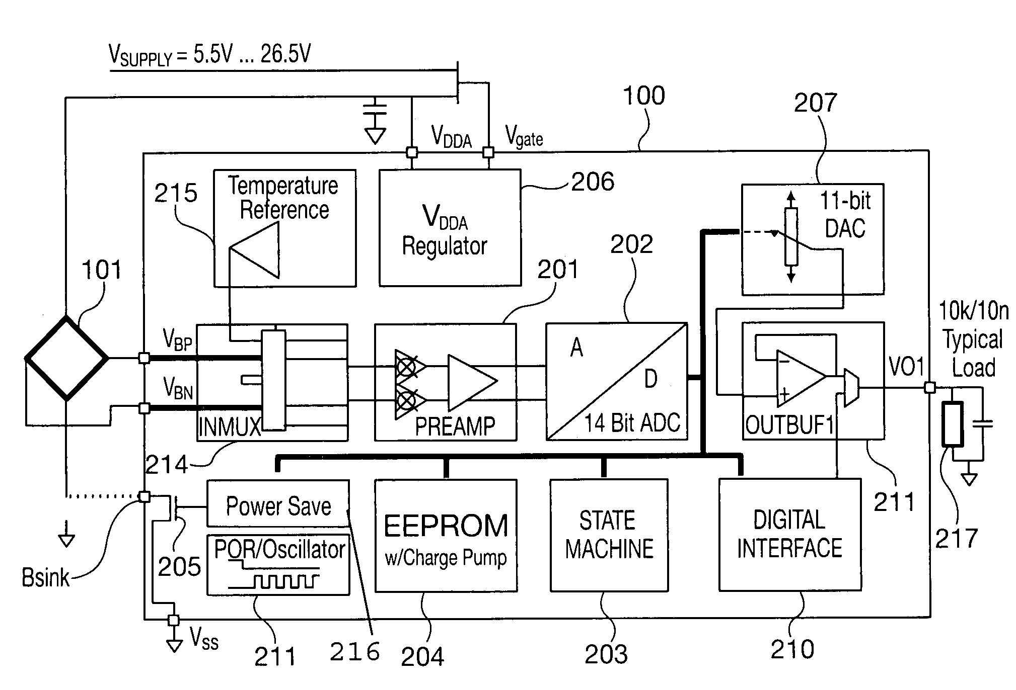
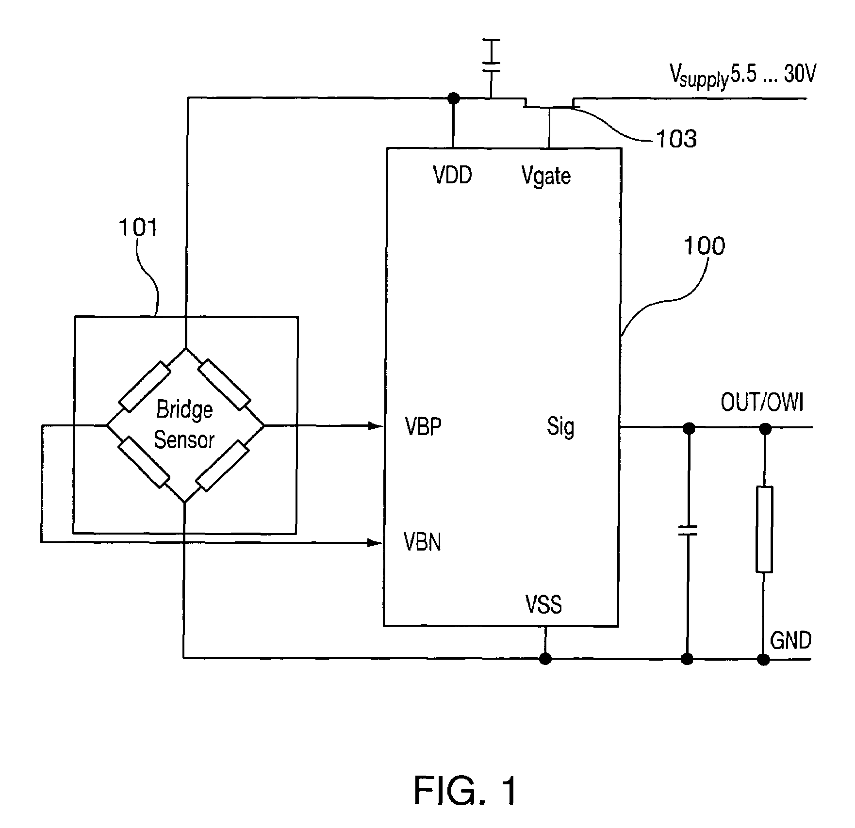
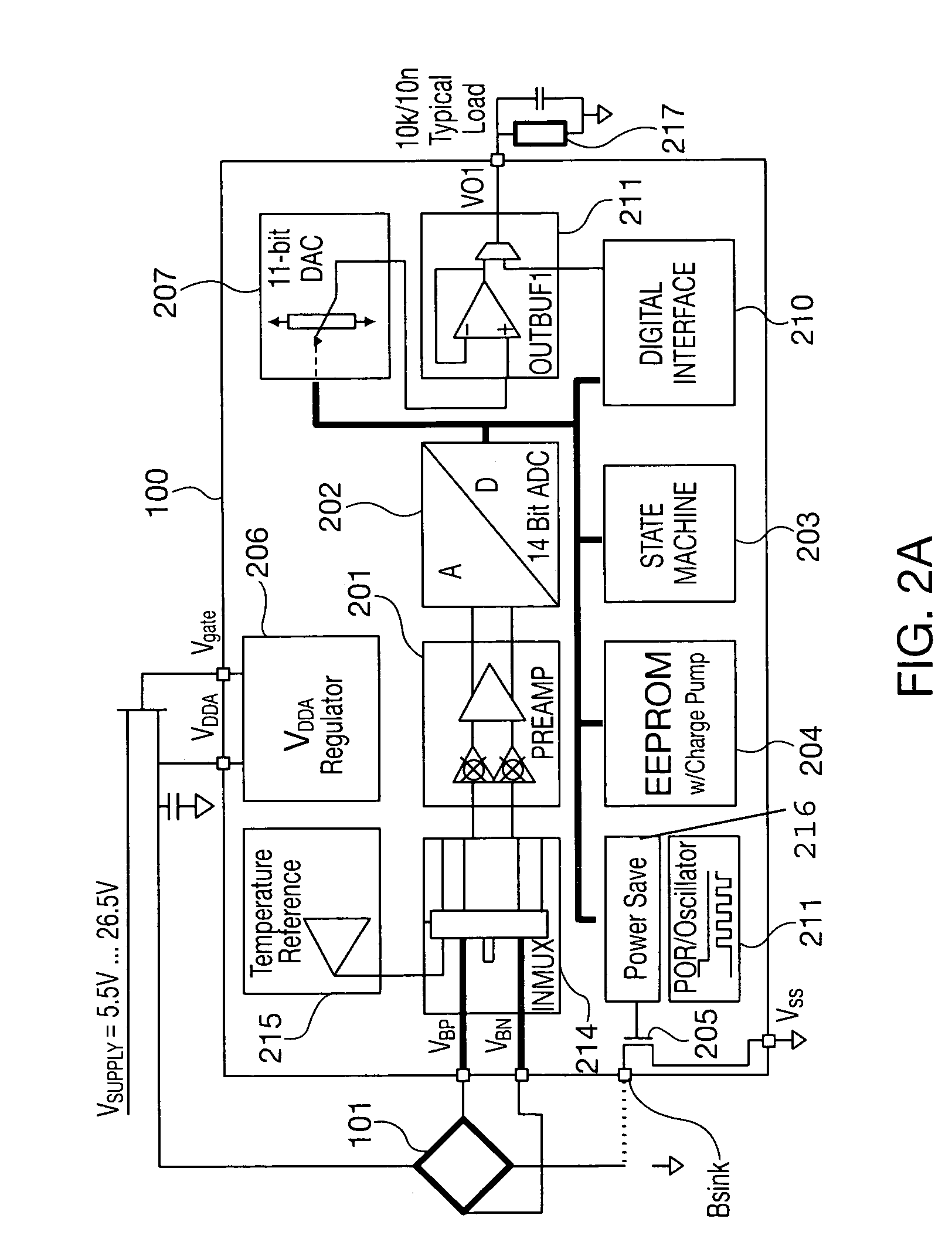
[0015]Referring now to FIG. 1, a simplified block diagram illustrates a sensor signal conditioner or sensor interface 100 and a bridge sensor 101. The expressions “sensor signal conditioner” and “sensor interface” are used interchangeably herein. The sensor interface 100 of the present invention is particularly well adapted for use as a resistive bridge sensor interface, and it can be used as a cost-effective solution for sensing in building automation, automotive, industrial, office automation and white goods applications. The sensor interface 100 preferably provides three selectable outputs, two analog and one digital, in order to provide versatility across many applications. For example, a ratiometric 5˜95% Vout signal (0.25˜4.75 Vout@ VDD=5V) is suitable for most building automation and automotive requirements. Typical office automation and white goods applications require a 0˜1Vout signal, which may be referenced to an internal bandgap. Direct interfacing to microprocessor cont...


PUM


Abstract

Apparatus and an accompanying method for calibrating a sensor signal conditioner coupled to a sensor. The signal conditioner sensor enables relatively easy and precise calibration of bridge sensors without the use of a microprocessor. When mated to a resistive bridge sensor, the sensor signal conditioner can digitally calibrate offset and gain, with an option to calibrate offset and gain coefficients and linearity over temperature. A second order compensation can be enabled for temperature coefficients of gain, offset or bridge linearity.

Description

CLAIM TO PRIORITY[0001]This application claims the benefit of our co-pending United States provisional patent application entitled “SENSOR CALIBRATION TECHNIQUE” filed Jan. 12, 2006 and assigned Ser. No. 60 / 758,318, which is incorporated by reference herein.BACKGROUND OF THE INVENTION[0002]1. Field of the Invention[0003]The present invention relates to an apparatus and method for calibrating a sensor signal conditioner coupled to a sensor, and more particularly relates to an apparatus and method for calibrating a sensor signal conditioner coupled to a bridge sensor without the use of an on-board microprocessor.[0004]2. Description of the Relevant Art[0005]Bridge circuit sensors are well known in the art, and they are widely used to sense changes, such as changes in pressure or acceleration. A typical bridge circuit sensor includes piezo-resistive elements that are mounted on a substrate, and the stresses induced in the piezo-resistive elements provide an electrical output. The elect...

Claims


Application Information

Patent Timeline
Patent Type & Authority Patents(United States)
IPC IPC(8): G01F25/00
CPCG01D18/008
Inventor HUBANKS, DAVIDHOFFMAN, ERIC JOSEPHCOOPER, FRANK GEORGE
Owner ZMD AMERICA
Learn More