Non-uniformity correction of images generated by focal plane arrays of photodetectors

a focal plane array and non-uniform correction technology, applied in the field of photodetectors, can solve the problems of non-uniform noise, non-uniform noise of electronic readout, non-uniform noise of image collection using certain arrays of infrared detectors (or sensors), etc., and achieve the effect of reducing residual non-uniformity

Active Publication Date: 2009-03-26
RAFAEL ADVANCED DEFENSE SYSTEMS
View PDF18 Cites 30 Cited by
  • Summary
  • Abstract
  • Description
  • Claims
  • Application Information

AI Technical Summary

Benefits of technology

[0014]Not wishing to be bound by any particular theory, it is noted that the present inventor has found that the gain coefficients used to correct the corrected image tend to be stable over time, thereby obviating the need to frequently re-calibrate the gain coefficients.
[0015]Typically, the calibration with a reference image to compute gain coefficients is a one-time calibration, though it is appreciated that periodically (e.g. every few weeks, months or years) a new reference image may be acquired and used to re-calibrate in order to help reduce residual non-uniformity.

Problems solved by technology

Imagery collected using certain arrays of infrared detectors (or sensors) suffers from non-uniformity noise due to a number of factors, including variations between detector elements in dark current (leakage current), offset (bias) and responsivity (gain).
Other sources of non-uniformity noise include electronic readout non-uniformities and non-uniformities of low spatial frequency including non-uniformities derived from device optics (e.g. due to the decrease in radiation from the center to the edge of the field of view,) and non-uniformities stemming from uneven cooling of detector elements.
In many situations, the non-uniformity noise adversely affects image quality.
Although the gain coefficients are generally stable, the offset coefficients drift and can require frequent calibration.

Method used


Image

  • Non-uniformity correction of images generated by focal plane arrays of photodetectors
  • Non-uniformity correction of images generated by focal plane arrays of photodetectors
  • Non-uniformity correction of images generated by focal plane arrays of photodetectors

Examples


examples

[0082]The following examples are to be considered merely as illustrative and non-limiting in nature. It will be apparent to one skilled in the art to which the present invention pertains that many modifications, permutations, and variations may be made without departing from the scope of the invention.

Experimental Methods and Results

[0083]The present inventors have performed experiments in order to demonstrate image correction techniques in accordance with some embodiments of the present invention.

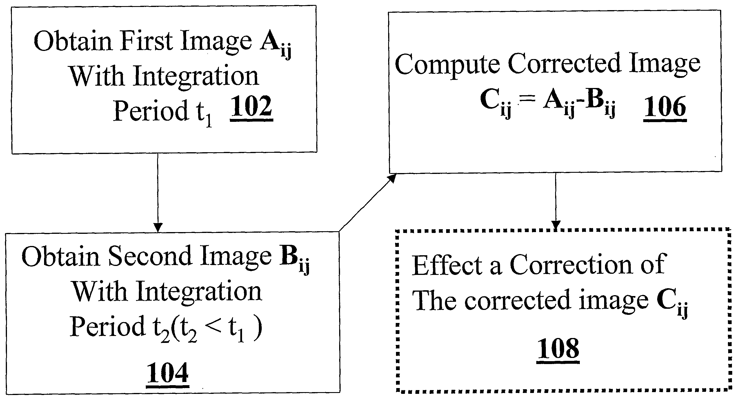
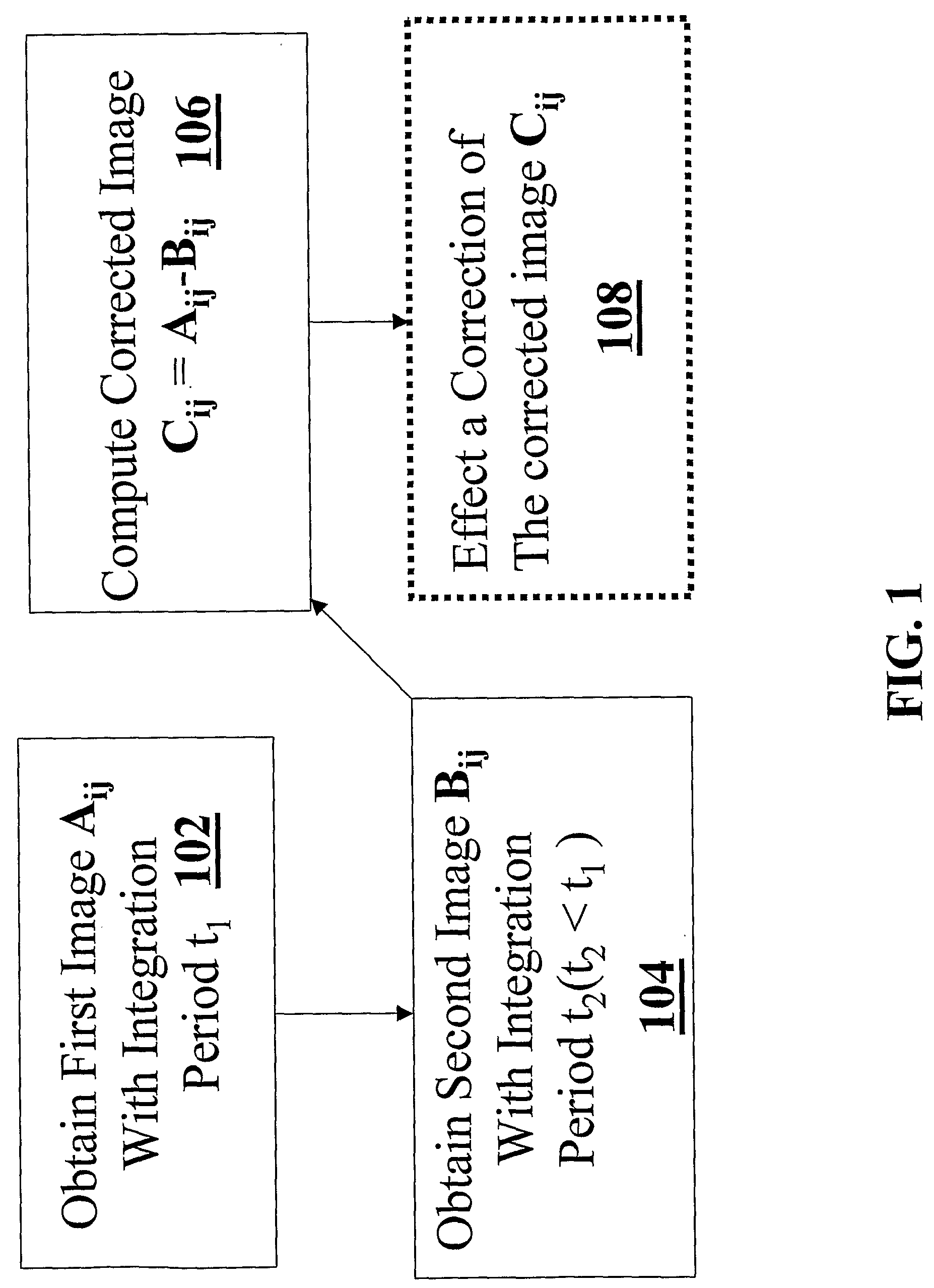
[0084]Experiments were conducted in order to examine the effectiveness of using a plurality of detected images having different integration periods to implement a non-uniformity correction. An infrared camera (Rafael and Elop, with InSb detector) was used, where the internal NUC of the infrared camera was disabled. Every series of image was recorded twice, first with a longer integration period (t1=about 1.5 ms) and then with a shorter integration period (t2=about 0.5 ms).

[0085]The digital...


PUM


Abstract

Methods and apparatus for effecting a non-uniformity correction of images of a scene obtained with an array of detector elements are disclosed. A first image of the scene having a first integration period is acquired using the array of detector elements. A second image of the scene having a different integration period is acquired, and a corrected image of the scene is generated by computing a difference of the images. In some embodiments, the first and second images are images of substantially identical scenes. According to some embodiments, the images are infrared images. Optionally, the corrected image is subjected to further correction using pixel dependent correction coefficients, such as gain coefficients. Exemplary image detection elements include but are not limited to InSb detector elements and ternary detector elements, such as InAlSb, MCT (Mercury Cadmium Telluride), and QWIP technology (Quantum Well Infrared Photodiodes). In some embodiments, the detector elements are cooled to a temperature substantially equal to an atmospheric boiling point of liquid nitrogen. Alternatively, the detector elements are cooled to a temperature below an atmospheric boiling point of liquid nitrogen, or any other operating temperature.

Description

FIELD OF THE INVENTION[0001]The present invention relates generally to photodetectors (e.g. infrared detectors), and more particularly to methods and systems for compensating for non-uniformities among detector elements of a staring detector array.BACKGROUND OF THE INVENTION[0002]Imagery collected using certain arrays of infrared detectors (or sensors) suffers from non-uniformity noise due to a number of factors, including variations between detector elements in dark current (leakage current), offset (bias) and responsivity (gain). Other sources of non-uniformity noise include electronic readout non-uniformities and non-uniformities of low spatial frequency including non-uniformities derived from device optics (e.g. due to the decrease in radiation from the center to the edge of the field of view,) and non-uniformities stemming from uneven cooling of detector elements. In many situations, the non-uniformity noise adversely affects image quality.[0003]A number of methods have been tr...

Claims


Application Information

Patent Timeline
Patent Type & Authority Applications(United States)
IPC IPC(8): G06T7/00
CPCG06T5/50G06T2207/10048G06T5/002H04N5/3656G06T5/007G06T2207/20224H04N5/33G06T5/006H04N25/674
Inventor MANGOUBI, SHMUELNAVEH, OVED
Owner RAFAEL ADVANCED DEFENSE SYSTEMS
Why Eureka
Try Eureka