RH vacuum refining bottom blowing powder injection device

A vacuum refining and powder spraying technology, applied in the field of iron and steel refining, can solve the problems of affecting operation stability, affecting the quality of molten steel, and low metallurgical efficiency of powder spraying, so as to improve operation safety, improve production quality, and facilitate continuous production Effect

Active Publication Date: 2012-07-11
NORTHEASTERN UNIV
View PDF5 Cites 22 Cited by
  • Summary
  • Abstract
  • Description
  • Claims
  • Application Information

AI Technical Summary

Problems solved by technology

like figure 1 The structure diagram of the RH-Injection method device is shown. The spray gun A is directly inserted into the molten steel to contact with the molten steel. The spray gun A as a consumable is expensive, but its service life is not long, which leads to an increase in the cost of the refining process; spray gun A When in use, the drop may touch the convex hull, causing huge vibration and seriously affecting the molten steel treatment plan and production scheduling; the stroke of the spray gun is constant, but the height of the molten steel level changes greatly, making the immersion of the spray gun A too deep or too shallow, affecting the operation The stability of the spray gun A is not conducive to production; the peeling or breaking of the spray gun A into the molten steel will seriously affect the quality of the molten steel; in case of power failure and other accidents, not only the spray gun A may be damaged, but the entire package of molten steel may also be scrapped
like figure 2 The structure diagram of the RH-PB method device is shown. The device is equipped with a powder injection component B on the side of the vacuum chamber. Although the shortcoming of the spray gun directly inserted into the molten steel is overcome, the nozzle is close to the liquid surface, which is easy to cause splashing, and the spraying Low efficiency of powder metallurgy

Method used


Image

  • RH vacuum refining bottom blowing powder injection device
  • RH vacuum refining bottom blowing powder injection device
  • RH vacuum refining bottom blowing powder injection device

Examples


Embodiment 1

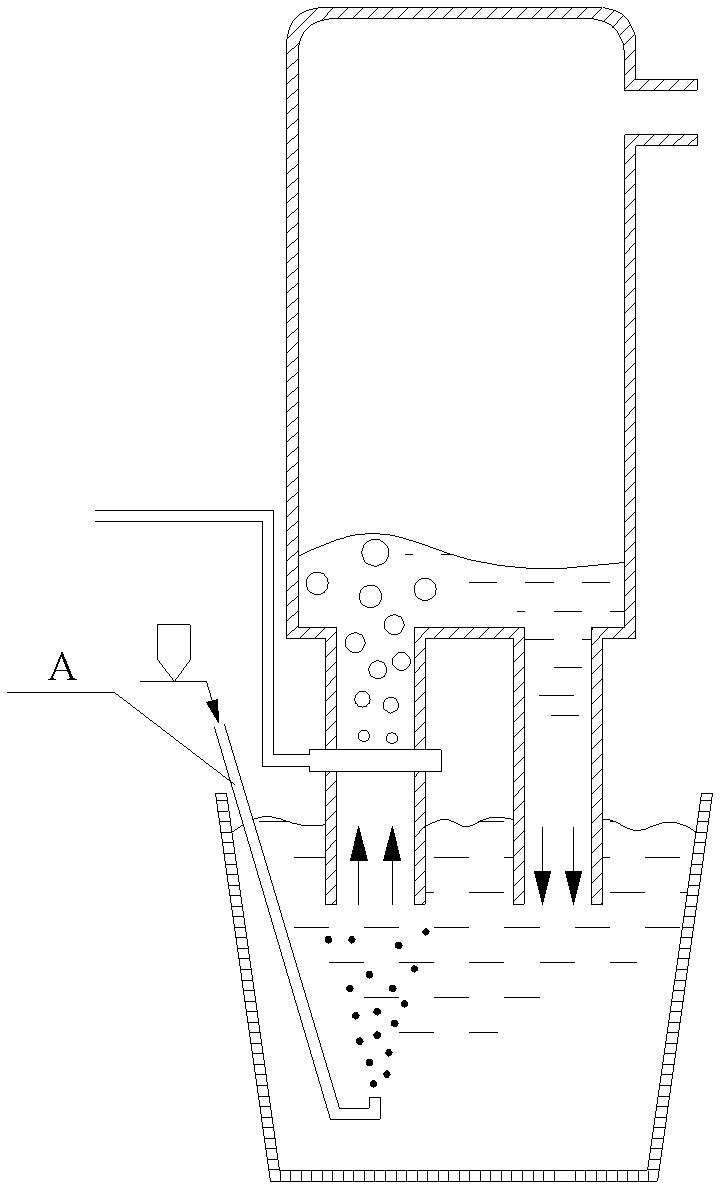
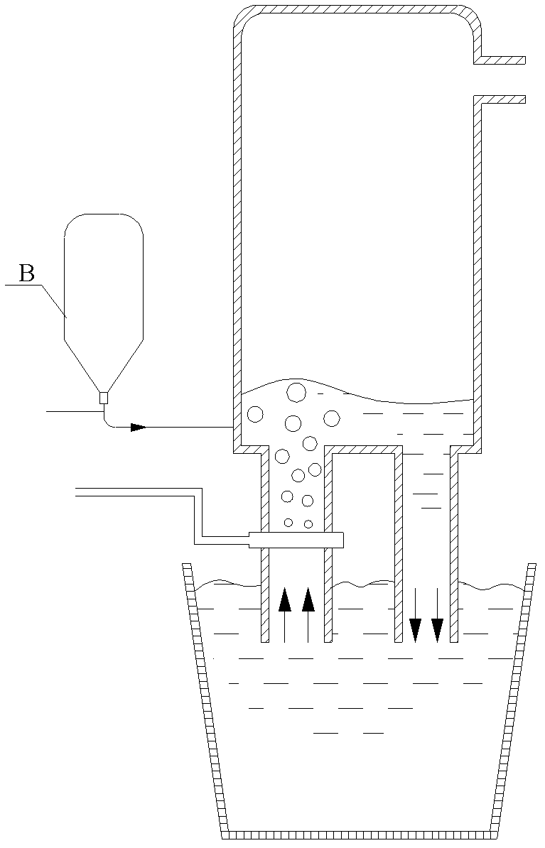
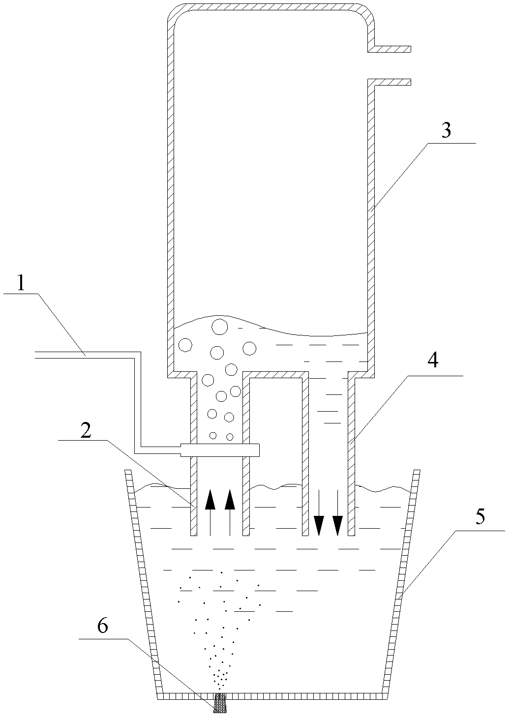
[0026] This embodiment designs a kind of RH vacuum refining bottom blowing powder spraying device, as image 3 As shown, it includes a driving gas system, a vacuum chamber 3, a ladle 5 and a bottom blowing powder member 6, the vacuum chamber 3 is arranged above the ladle 5, and the driving gas system includes a driving gas channel 1 and an air compressor connected to the driving gas channel 1 , the bottom of the vacuum chamber 3 is provided with an ascending pipe 2 and a descending pipe 4, the ascending pipe 2 and the descending pipe 4 extend into the molten steel in the ladle 5 and have an opening at the end, the driving gas channel 1 communicates with the ascending pipe 2, and the bottom blowing powder The component 6 includes a powder spraying element 7 and a gas storage chamber 11. The powder spraying element 7 is made of refractory material. The powder spraying element 7 is covered with a steel sleeve 9, and both sides of the steel sleeve 9 are provided with protruding con...

Embodiment 2

[0029]It is basically the same as Example 1, except that the number of bottom blowing powder spraying components 6 is 2, which are symmetrically arranged at the bottom of the ladle 5, that is, the double-hole bottom blowing powder spraying refining structure, that is, as Figure 7 As shown; the number of straight line slits 8a is 16.

[0030] The device is used for circulating degassing bottom blowing powder refining, the powder particle size is 200~400 mesh, the dry argon pressure is 0.6Mpa, the powder gas ratio is 8, and the smelting time is 20min, the stirring intensity of the ladle 5 is enhanced, and the temperature composition in the molten pool uniform, and the refining cycle is shortened, the penetration ratio of the powder measured after treatment is greater than 90%, and it can be achieved after treatment w [H]w [N]w [C]w [S]w [P]<0.002%, saving 1~10% of electric energy.

Embodiment 3

[0032] It is basically the same as Embodiment 1, except that the powder spraying element 7 of the bottom blowing powder spraying member 6 is provided with an annular gap 8b concentric with the center of the powder spraying component 7, and the number of annular gaps 8b is 2, such as Figure 8 , Figure 9 Shown; the gap width is 0.14mm.

[0033] The device is used for circulating degassing bottom blowing powder refining. The particle size of the powder is 200~400 mesh, the dry argon pressure is 0.6Mpa, the powder gas ratio is 6, and the smelting is 35min. After the treatment, the penetration ratio of the powder is 93%. After treatment, w[H]<0.00015%, w[N]<0.004%, w[C]<0.003%, w[S]<0.001%, w[P]<0.002%, saving 1~10% of electric energy .


PUM

PropertyMeasurementUnit
widthaaaaaaaaaa

Abstract

The invention relates to an RH vacuum refining bottom blowing powder injection device. The device comprises a driving gas system, a vacuum chamber, a steel ladle and a bottom blowing powder injection member, wherein the vacuum chamber is formed above the steel ladle; the driving gas system comprises a driving gas channel and an air compressor connected with the driving gas channel; an ascending pipe and a descending pipe are arranged at the bottom of the vacuum chamber and stretch into molten steel; the driving gas channel is communicated with the ascending pipe; the bottom blowing powder injection member comprises a powder injection element and a gas storage chamber; a steel sleeve is sleeved outside the powder injection element; the gas storage chamber is fixed below the powder injection element; a powder gas flow conveying pipe at the port of the gas storage chamber is connected with a powder injection system; a gap is formed on the powder injection element; one or two bottom blowing powder injection members are arranged at the bottom of the steel ladle; the distance between the bottom blowing powder injection member and the center of the bottom of the steel ladle is 0 to 0.9 time the radius of the bottom of the steel ladle; and the powder injection element penetrates through the bottom of the steel ladle. The device enhances a stirring effect and improves the quality of steel by combining vacuum refining, molten steel circular flow and bottom blowing powder injection refining.

Description

technical field [0001] The invention belongs to the technical field of iron and steel refining, in particular to a bottom blowing powder injection device for RH vacuum refining. Background technique [0002] The RH cycle vacuum degassing method is commonly used in iron and steel refining. This method combines vacuum refining with molten steel circulation. Oxygen cycle vacuum degassing (RH-OB) method; the second is to combine powder spraying metallurgy with additional powder spraying function, such as Nippon Steel’s cycle degassing powder spraying (RH-PB) method. The use of circulating degassing and powder spraying can realize vacuum degassing, reduce impurities, uniform composition and temperature, and can realize functions such as powder spraying desulfurization and dephosphorization, and the hydrogen content in steel after treatment w [H]<0.0002%, dehydrogenation rate 50%~80%, nitrogen content w [N]<0.004%, nitrogen removal rate 15%~25%, oxygen content w [o]=0.002...

Claims


Application Information

Patent Timeline
Patent Type & Authority Applications(China)
IPC IPC(8): C21C7/10C21C7/04F27D3/18
Inventor 朱苗勇程中福娄文涛付贵勤盛国良
Owner NORTHEASTERN UNIV
Why Eureka
Try Eureka