Multifunctional static or semi-static photovoltaic skylight and/or methods of making the same

a photovoltaic skylight and semi-static technology, applied in the field of solar photovoltaic systems, can solve the problems of large number of c-si wafers dominated the cost of the overall photovoltaic module, system difficulty in competing with other photovoltaic solutions on a cost per watt basis, and current concentrated photovoltaic systems use expensive high efficiency multi-junction solar cells, etc., to achieve the effect of less silicon material and dominating the cost of the overall

Inactive Publication Date: 2014-04-03
GUARDIAN GLASS LLC
View PDF6 Cites 30 Cited by
  • Summary
  • Abstract
  • Description
  • Claims
  • Application Information

AI Technical Summary

Benefits of technology

[0003]Photovoltaic devices are known in the art (e.g., see U.S. Pat. Nos. 6,784,361, 6,288,325, 6,613,603, and 6,123,824, the disclosures of which are hereby incorporated herein by reference). Some conventional mainstream photovoltaic modules use a large number of crystalline silicon (c-Si) wafers. The inclusion of the large number of c-Si wafers tends to dominate the cost of the overall photovoltaic module. Indeed, about 60% of the costs involved in the production of conventional photovoltaic modules is related to the c-Si solar cells. To address this issue, concentrated photovoltaic (CPV) systems have been proposed, in which the sunlight is to be focused with concentration ratios of 100× to 1000×. Calculations suggest that a concentration ratio of approximately 10× should enable a photovoltaic system to be produced that uses at least 90% less silicon material.

Problems solved by technology

The inclusion of the large number of c-Si wafers tends to dominate the cost of the overall photovoltaic module.
Unfortunately, however, current concentrated photovoltaic systems use expensive high efficiency multi-junction solar cells, expensive dual-axis tracking systems, and / or relatively expensive concentrating optics.
Therefore, these systems have difficulty competing with other photovoltaic solutions on a cost per watt basis.

Method used


Image

  • Multifunctional static or semi-static photovoltaic skylight and/or methods of making the same
  • Multifunctional static or semi-static photovoltaic skylight and/or methods of making the same
  • Multifunctional static or semi-static photovoltaic skylight and/or methods of making the same

Examples


Embodiment Construction

[0048]Photovoltaic devices such as solar cells convert solar radiation into usable electrical energy. The energy conversion occurs typically as the result of the photovoltaic effect. Solar radiation (e.g., sunlight) impinging on a photovoltaic device and absorbed by an active region of semiconductor material generates electron-hole pairs in the active region.

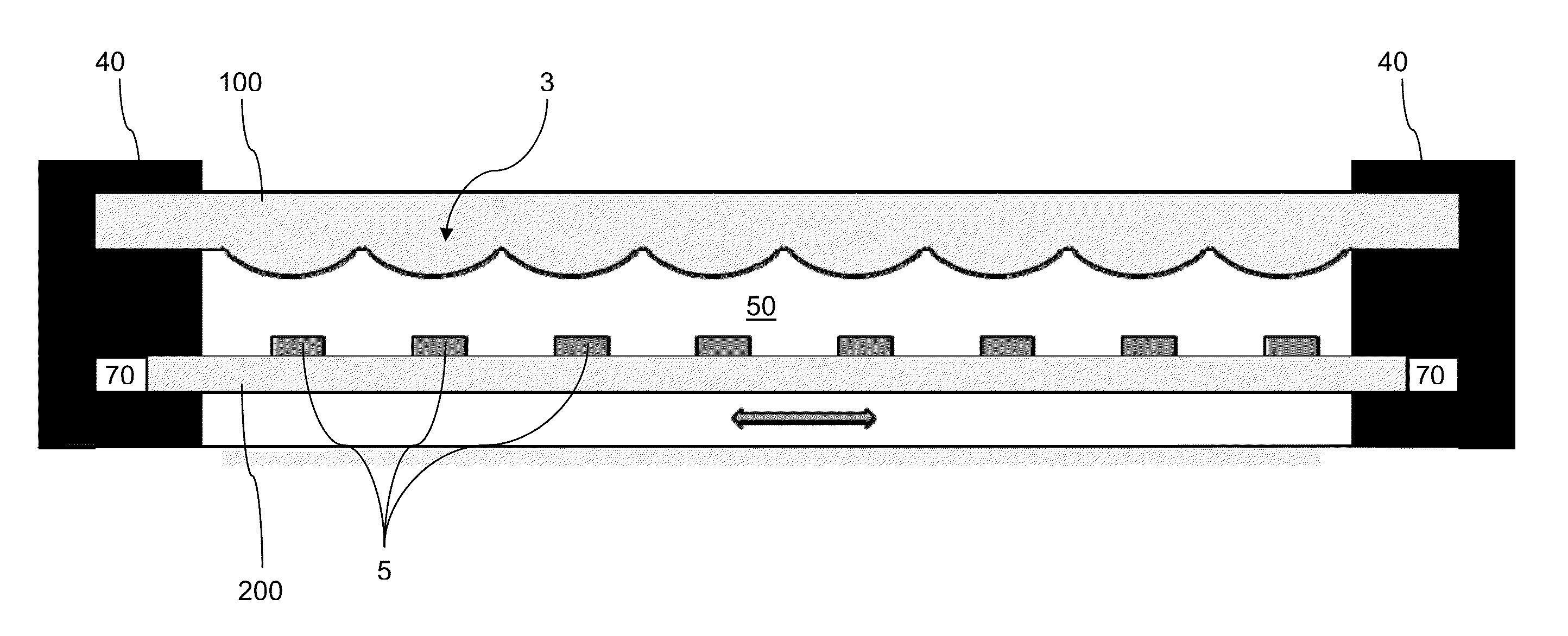
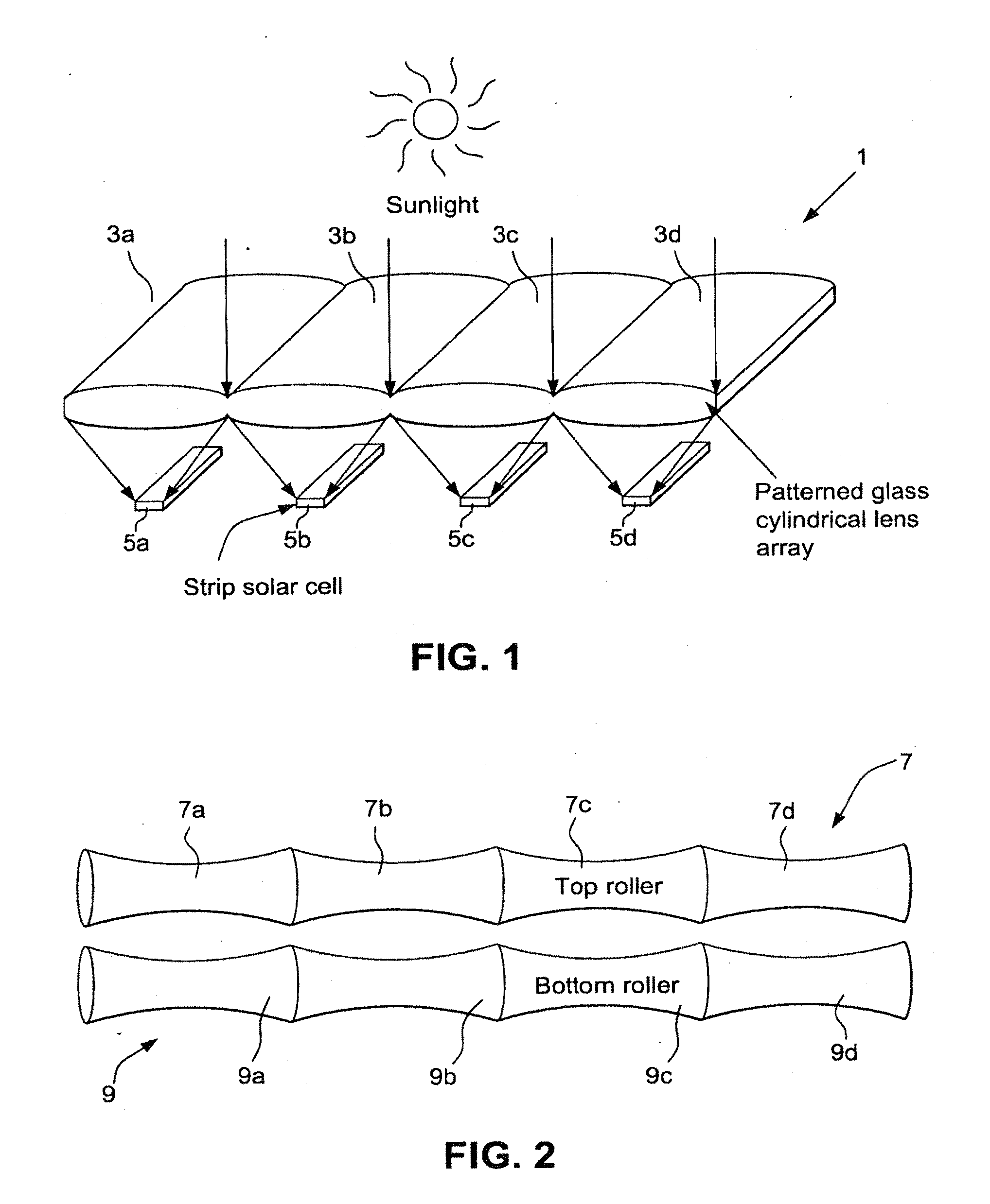
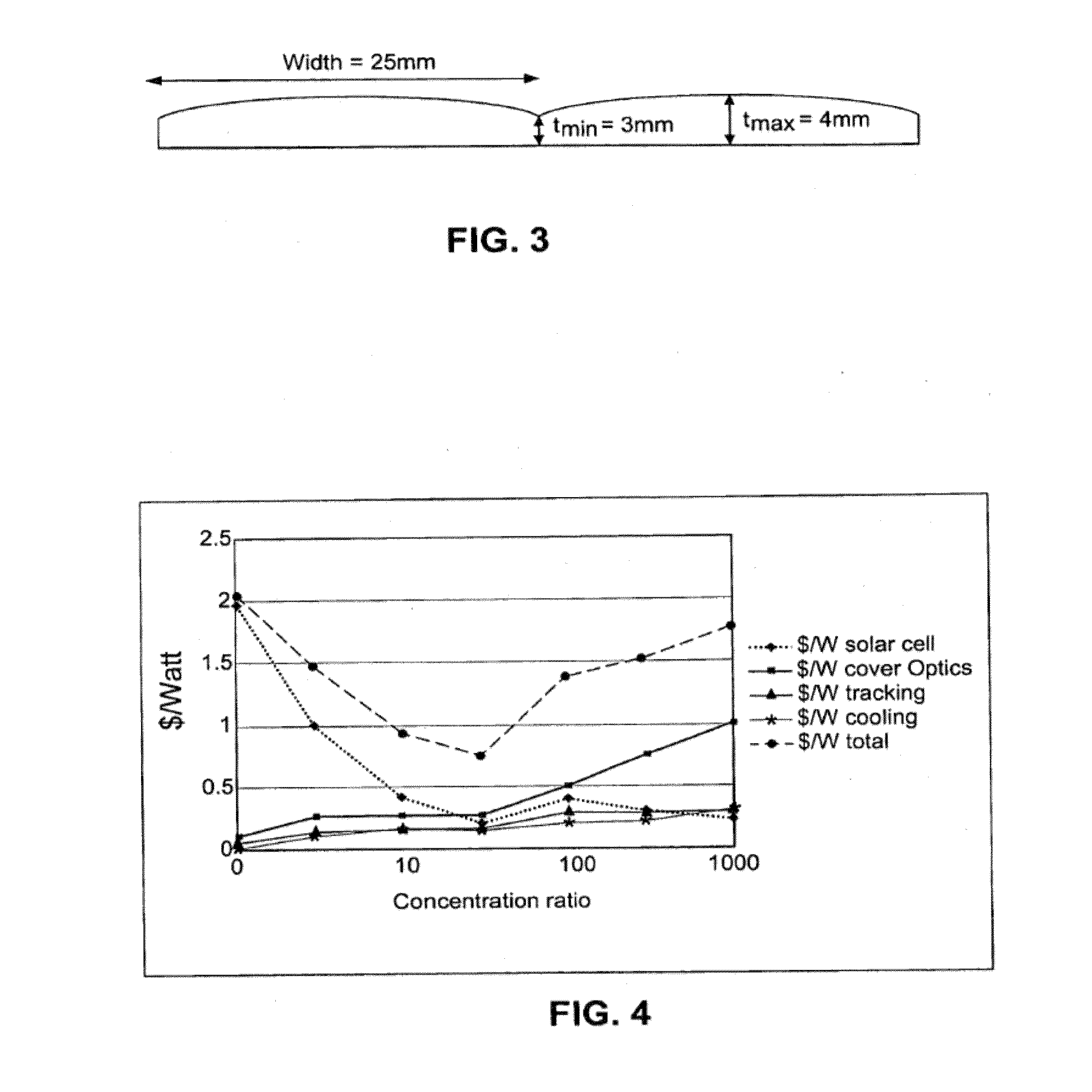
[0049]Certain example embodiments of this invention relate to patterned glass that can be used as a cylindrical lens array in a concentrated photovoltaic application, and / or methods of making the same. In certain example embodiments, the lens arrays may be used in combination with strip solar cells and lateral displacement tracking systems. That is, in certain example embodiments, lenses in the lens array may be arranged so as to concentrate incident light onto respective strip solar cells, and the solar cell substrate is controlled a lateral displacement tracking system that is programmed to follow the East-West movement of the...


PUM

PropertyMeasurementUnit
heightaaaaaaaaaa
thicknessaaaaaaaaaa
thicknessaaaaaaaaaa

Abstract

Improved building-integrated photovoltaic systems according to certain example embodiments may include concentrated photovoltaic skylights or other windows having a cylindrical lens array. The skylight may include an insulated glass unit, which may improve the Solar Heat Gain Coefficient (SHGC). The photovoltaic skylight and lens arrays may be used in combination with strip solar cells. Arrangements that involve lateral displacement tracking systems, or static systems (e.g., that are fixed at one, two, or more predefined positions) are contemplated herein. Such techniques may advantageously help to reduce cost per watt related, in part, to the potentially reduced amount of semiconductor material to be used for such example embodiments. A photovoltaic skylight may permit diffuse daylight to pass through into an interior of a building so as to provide lighting inside the building, while the strip solar cells absorb the direct sunlight and convert it to electricity, providing for SHGC tuning.

Description

CROSS-REFERENCES TO RELATED APPLICATIONS[0001]This application is a continuation-in-part of U.S. application Ser. No. 13 / 477,400 filed May 22, 2012, which in turn is a continuation-in-part of U.S. application Ser. No. 12 / 662,624 filed Apr. 26, 2010, the entire contents of which are hereby incorporated herein by reference.FIELD OF THE INVENTION[0002]Certain example embodiments of this invention relate to improved solar photovoltaic systems, and / or methods of making the same. More particularly, certain example embodiments of this invention relate to building-integrated photovoltaic systems including concentrated photovoltaic skylights having a cylindrical lens array, and / or methods of making the same.BACKGROUND AND SUMMARY OF EXAMPLE EMBODIMENTS OF THE INVENTION[0003]Photovoltaic devices are known in the art (e.g., see U.S. Pat. Nos. 6,784,361, 6,288,325, 6,613,603, and 6,123,824, the disclosures of which are hereby incorporated herein by reference). Some conventional mainstream photo...

Claims


Application Information

Patent Timeline
Patent Type & Authority Applications(United States)
IPC IPC(8): E04D13/03H01L31/052F24S23/30
CPCH01L31/0524E04D13/03Y02E10/52G02B3/005G02B3/0056G02B3/0062H01L31/0521C03B13/08H01L31/0543H01L31/0547H02S20/26Y02B10/20F24S23/31Y02B10/10
Inventor DEN BOER, WILLEMWENG, JIAN-GANGAKKASHIAN, ERIC WALTERVEERASAMY, VIJAYEN S.THOMSEN, SCOTT V.
Owner GUARDIAN GLASS LLC
Why Eureka
Try Eureka