Differential fluid pressure measurement apparatus

Active Publication Date: 2009-08-25
SENSATA TECHNOLOGIES INC
View PDF7 Cites 21 Cited by
  • Summary
  • Abstract
  • Description
  • Claims
  • Application Information

AI Technical Summary

Benefits of technology

[0003]It is an object of the present invention to provide a differential fluid pressure sensor that can easily be oriented so that the diaphragm surfaces are perpendicular to the direction of gravity. Another object of the invention is the provision of a differential fluid pressure sensor that is compact and one that can be made of less expensive materials than typically required. Yet another object of the invention is the provision of a differential fluid pressure sensor whose structure allows the use of time saving assembly operations.
[0006]In the preferred embodiment of the invention described in detail below, the sense element is connected with wire bonds to one end of terminal pins with the other end of the pins bonded to a printed circuit board having conditioning circuits and this in turn is connected to connector terminals by means of metal springs. A sealant is placed around the pins to prevent oil leaks through the pin / base interface.

Problems solved by technology

Further, mounting of the diaphragms so that they face in opposite directions can result in having to use separate housing members that each needs to be robust with the sensed media.

Method used


Image

  • Differential fluid pressure measurement apparatus
  • Differential fluid pressure measurement apparatus
  • Differential fluid pressure measurement apparatus

Examples


first embodiment

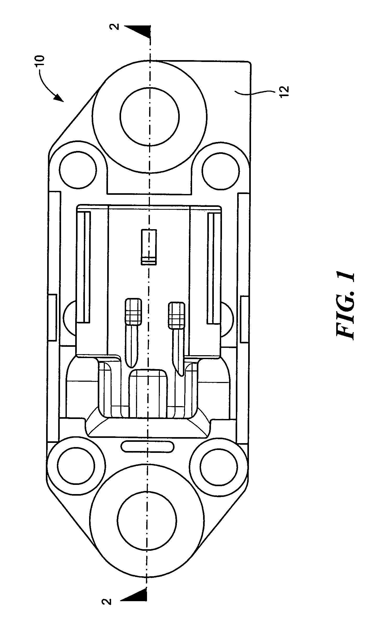
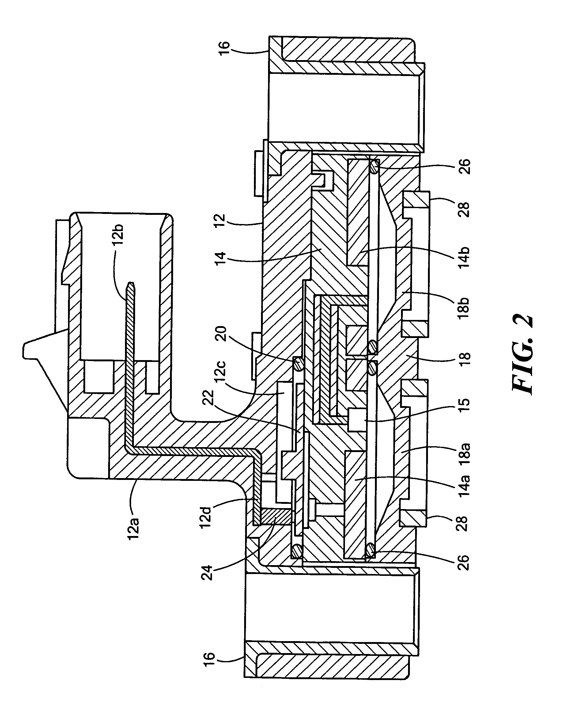
[0026]A generally U-shaped passageway 14g is formed through the base of the module leading from an opening in surface 14c in window 14f of disc 14a to an opening in surface 14c in window 14f of disc 14b. According to a feature of the first embodiment, the bight portion of the U-shaped passageway is formed by a tube 14h of brass or other suitable material. An enlarged opening 14k at one end of the passageway in widow 14f of disc 14b is provided for placement of a pressure sense element, such as a piezoresistive element 15, as seen more clearly in FIGS. 5 and 6, attached to flange 14j of enlarged opening 14k by silicone-based adhesive material or other suitable adhesive material 15a. Wires 15c are bonded between sense element 15 and respective electrical terminal pins 15d. Adhesive and gel are used to provide a pressure tight seal between the terminal pins and the surrounding plastic.

[0027]Suitable adhesive material 14l of epoxy or silicone-based material is applied to the outer surfa...

second embodiment

[0032]With regard to ceramic, sensor element module 240, FIGS. 13 and 14, can be formed of alumina, for example and formed with a corresponding U-shaped passageway 242 opening through bottom surface 244 in the same manner as in module 140 embodiment. The passageway is closed by a cover 246 of alumina or the like which can be attached to module 240 with glass. Oil fill holes 256 correspond to oil fill holes 156 of the In this case, the oil fill holes can be sealed with a plastic plug. Terminal pins mounted with glass can be used in this embodiment as well.


PUM

PropertyMeasurementUnit
flexibleaaaaaaaaaa
pressure responsiveaaaaaaaaaa
pressureaaaaaaaaaa

Abstract

A differential liquid pressure sensor (10) has an upper housing (12) that mounts a connector portion (12a) and receives in a recess a sense element module (14). The sense element module is a body in which a generally U-shaped oil filled passageway (14h) is formed with openings at opposite ends provided on respective first and second diaphragm mounting surfaces. A fluid pressure sense element, such as a piezoresistive sense element (15) is disposed in one of the passageway openings and flexible metal diaphragms (14a, 14b) are mounted on the respective diaphragm mounting surfaces of the module facing a common direction. A lower housing (18) having first and second port connections for the respective diaphragms is disposed on the lower surface of the module.

Description

FIELD OF THE INVENTION[0001]This invention relates generally to apparatus for measuring fluid pressure and more particularly to such apparatus providing a media isolated differential pressure sensor using two diaphragms for placement in fluid communication with respective high and low pressure sources.BACKGROUND OF THE INVENTION[0002]Solid state pressure sense elements, such as piezoresistive pressure sense elements, are often isolated from the sensed media by a flexible metal diaphragm robust to the media to protect such sense elements. An incompressible fluid, typically silicone oil, is used to transfer pressure from the diaphragm to the sense element. It is conventional to provide first and second diaphragms facing opposite directions with the sense element disposed therebetween. To reduce the accumulation of substances, such as soot, water, condensate from the media on the diaphragm that could damage the sensor, it is often required to place the diaphragms in a drainable orienta...

Claims


Application Information

Patent Timeline
Patent Type & Authority Patents(United States)
IPC IPC(8): G01L13/02
CPCG01L13/025G01L13/00G01L7/08G01L9/06
Inventor HADJILOUCAS, COSTASWILLNER, ANDREWAMATRUDA, ANDREWKRAJEWSKI, GEORGE
Owner SENSATA TECHNOLOGIES INC
Why Eureka
Try Eureka