Reaction method using microreactor

a microreactor and reaction method technology, applied in chemical/physical processes, biological material analysis, liquid-gas reaction processes, etc., can solve the problems of large limitation of the range of possible reaction changes, the inability to cause optimal reactions, and the inability to control the reaction rate. , to achieve the effect of reducing the trouble of disassembly cleaning, reducing the frequency of cleaning, and controlling the reaction ra

Inactive Publication Date: 2009-08-25
FUJIFILM CORP +1
View PDF15 Cites 6 Cited by
  • Summary
  • Abstract
  • Description
  • Claims
  • Application Information

AI Technical Summary

Benefits of technology

[0011]The present invention was made in view of such a situation as described above and has as its object the provision of a reaction method using a microreactor which can adapt to various reactions and changes in conditions with the same microreactor and can minimize troubles and the frequency of disassembly cleaning because a reaction channel is prevented from being clogged and blocked with coagulated matter and precipitates formed by a reaction.

Problems solved by technology

This means that as the scale of a microspace is reduced, mixing proceeds accordingly due to the diffusion of molecules even when the reaction fluids are not positively mixed, with the result that the reaction tends to occur easily.
When a microreactor designed on the basis of such a basic principle is incorporated in a manufacturing process, because the opening width of the reaction channel is optimally designed according to the reaction characteristics (diffusion rate and reaction rate) of the fluids, it is impossible to cause an optimum reaction if fluids of different reaction characteristics are intended for a reaction with the same microreactor.
Even if a reaction is made possible to some extent, the range of possible reaction changes, condition changes or changes of the product characteristics are greatly limited.
Therefore, it is necessary to perform operations, such as using the manufacturing line as a dedicated line and replacing the microreactor with an appropriate one according to the reaction and conditions or product characteristics, providing the disadvantage that equipment cost rises and time losses due to replacement occur.
Furthermore, what poses a problem in a case where a reaction involving coagulation and precipitation occurs in the reaction channel is that coagulated matter and precipitates formed by the reaction adhere to the wall surface of the reaction channel and are deposited on it, thereby clogging the reaction channel.
This is not an essential solution.
As described above, a reaction obtained by use of a conventional microreactor has the defect that clogging troubles occur frequently and the disassembly cleaning to eliminate clogging troubles must be frequently performed.

Method used


Image

  • Reaction method using microreactor
  • Reaction method using microreactor
  • Reaction method using microreactor

Examples


example 1

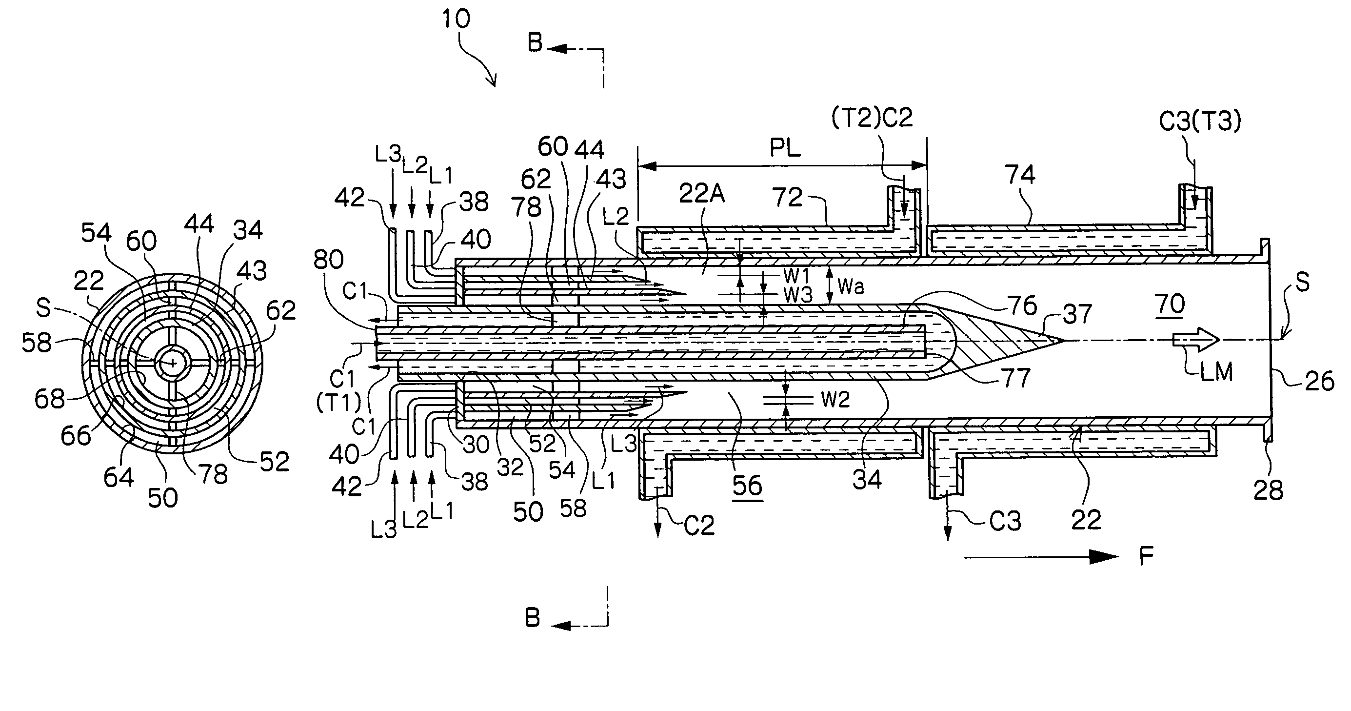
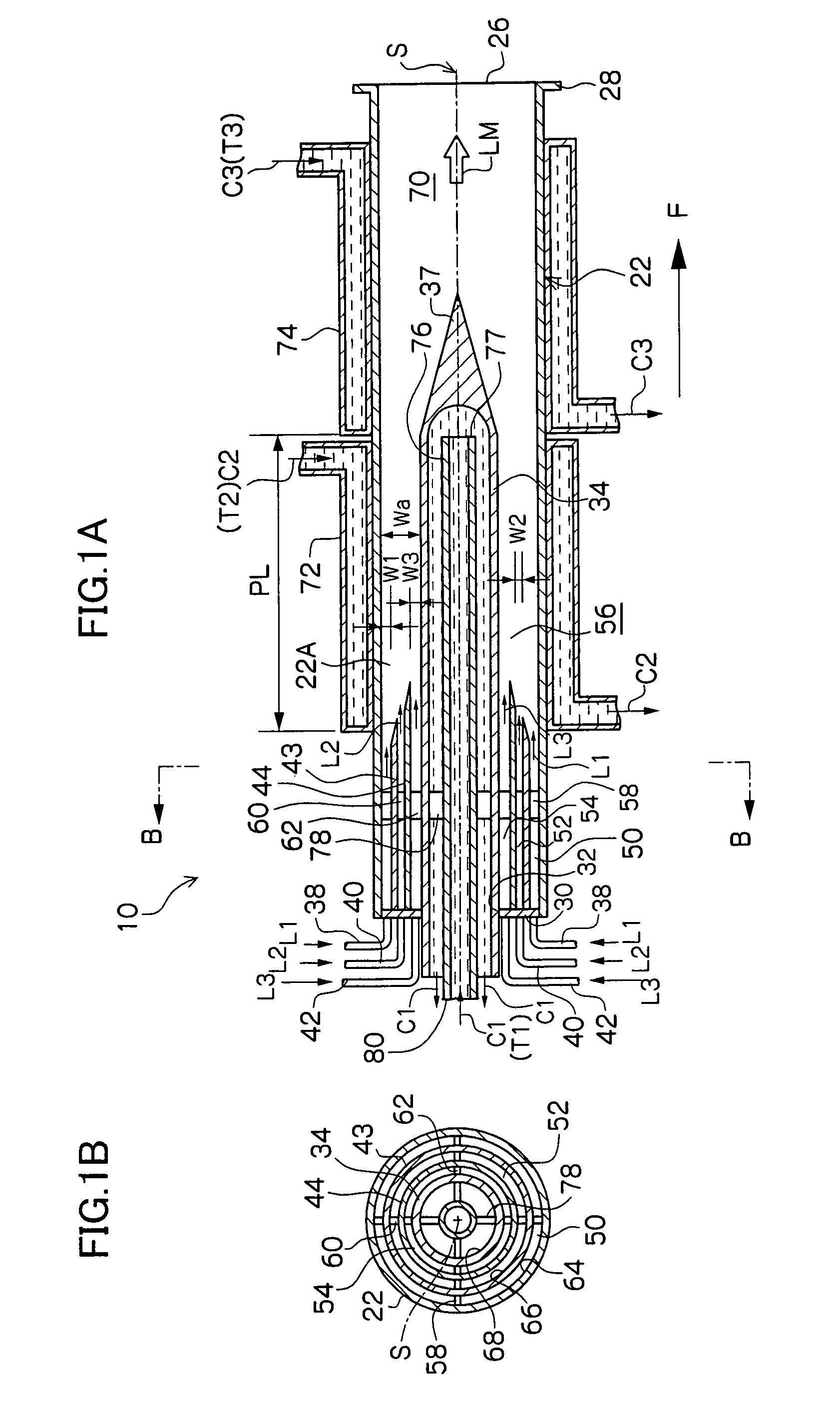
[0074]In this example, by use of a microreactor provided with four fluid supply routes which are formed as a multicylindrical structure having a co-axis, a reaction which involves the generation of fine particles silver chloride (AgCl) was caused to occur. Among four fluid supply routes, the innermost fluid supply route which comes into contact with the inner peripheral wall surface and outer peripheral wall surface of the reaction channel 56 and the outermost fluid supply route were each supplied with distilled water as a fluid not participating in the reaction, the second fluid supply route from the inside was supplied with a silver nitrate fluid (AgNO3), and the third fluid supply route from the inside was supplied with a sodium chloride fluid (NaCl). The opening width of the reaction channel 56 was 225 μm.

[0075]In the experiment, 0.05 mol / l of silver nitrate fluid and 0.05 mol / l of sodium chloride fluid were used, and each fluid was caused to contain 0.06 wt % low molecular weig...

example 2

Example of a Reaction Using Fluorine Gas

[0081]In this example of the present invention, a fluorination reaction was caused to occur by use of a stainless steel microreactor as shown in FIG. 6, which is provided with four fluid supply routes formed as a multicylindrical structure having a co-axis (opening width of the reaction channel 56: 225 μm).

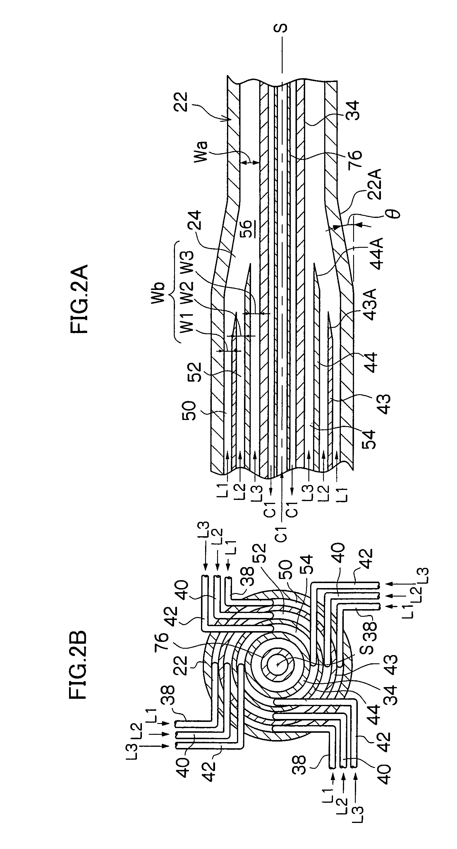
[0082]A cooling medium at −20° C. was circulated as the heat medium C1 shown in FIGS. 2A and 2B in order to control the reaction temperature, and perfluorohexane which is a solvent not participating in the reaction was caused to flow as the fluid L1 of FIG. 6. Next, 10 vol. % fluorine gas in nitrogen was caused to flow (10 ml / minute) as the fluid L2, and ethyl acetoacetate diluted with F-113 (1,1,2-richloro-trifluoroethane) (concentration: 10 wt. %) was caused to flow as the fluid L3 at a flow rate of 5 ml / h.

[0083]When a reaction liquid thus obtained was analyzed by use of high-speed liquid chromatography, it was found that 2-ethyl fluoroace...

example 3

Example of Synthesis of Organic Pigment

[0085]In this example of the present invention, a reaction to synthesize an organic pigment of the following reaction formula was caused to occur by use of a stainless steel microreactor as shown in FIG. 8, which is provided with six fluid supply routes formed as a multicylindrical structure having a co-axis (opening width of the reaction channel 56: 300 μm).

[0086]

[0087]Silicon oil heated to 180° C. was circulated as the heat medium C1 shown in FIGS. 1A and 1B in order to control the reaction temperature, and 1,2-dichlorobenzene which is a solvent at 80° C. was caused to flow as the fluid L1 of FIG. 8. Next, as the fluid L2 of FIG. 8, a solution obtained by causing 37.9 g (0.1 mol) of the above compound (A) to be suspended in 300 ml of 1,2-dichlorobenzene at 80° C. was dissolved in 300 ml of 1,2-dichlorobenzene and heated to 80° C., and this solution was caused to flow each time at a flow rate of 6 ml / minute by use of a piston pump.

[0088]When a...


PUM

PropertyMeasurementUnit
opening widthaaaaaaaaaa
inclination angleaaaaaaaaaa

Abstract

In a reaction caused by using a microreactor which provides a plurality of supply routes in communication with one reaction channel as a multicylindrical structure having a co-axis and causes a plurality of fluids L1, L2, L3 to flow together in the reaction channel via the respective fluid supply routes, whereby these fluids L1, L2, L3 are coaxially laminated and caused to flow as laminar flows whose sections orthogonal to the co-axis are annular and the fluids are diffused together in a normal direction of contact interfaces thereof to cause the reaction, among the plurality of laminated fluids L1, L2, L3, at least one fluid is constituted by a fluid not participating in the reaction of other fluids.

Description

BACKGROUND OF THE INVENTION[0001]1. Field of the Invention[0002]The present invention relates to a reaction method using a microreactor, particularly to an apparatus which manufactures materials and products in the fields of the chemical industry and medical product industry, and more particularly to a reaction method using a microreactor by the reaction of fluids which causes a plurality of fluids to join together in one reaction channel via respective fluid supply routes, whereby these fluids are caused to flow as laminar flows in the shape of thin layers and the fluids are diffused together in a normal direction of contact interfaces thereof to cause a reaction.[0003]2. Description of the Related Art[0004]In recent years, in the chemical industry and the medical product industry related to the manufacturing of medical products, reagents, etc., the development of new manufacturing processes using a microcontainer called a micromixer or microreactor has been pushed forward with. A ...

Claims


Application Information

Patent Timeline
Patent Type & Authority Patents(United States)
IPC IPC(8): G01N35/08B01F15/00B01L3/02G01N35/00B01D11/04B01F5/04B01F13/00B01J19/00B01J19/26C07B61/00C07C51/41C07C53/126C07C67/307C07C69/716C09B43/132G03C1/015G03C1/035G03C1/498
CPCB01F5/0453B01F13/0062B01F13/0066B01J19/0093B01F5/046Y10T436/11B01J2219/00788G03C1/015G03C1/035G03C1/49809Y10T436/117497G03C2200/09G03C2001/03517B01F25/3132B01F25/31324B01F33/3011B01F33/3012
Inventor NAGASAWA, HIDEHARUMAE, KAZUHIRO
Owner FUJIFILM CORP
Why Eureka
Try Eureka