Reaction method using microreactor
a microreactor and reaction method technology, applied in chemical/physical processes, biological material analysis, liquid-gas reaction processes, etc., can solve the problems of large limitation of the range of possible reaction changes, the inability to cause optimal reactions, and the inability to control the reaction rate. , to achieve the effect of reducing the trouble of disassembly cleaning, reducing the frequency of cleaning, and controlling the reaction ra
- Summary
- Abstract
- Description
- Claims
- Application Information
AI Technical Summary
Benefits of technology
Problems solved by technology
Method used
Image
Examples
example 1
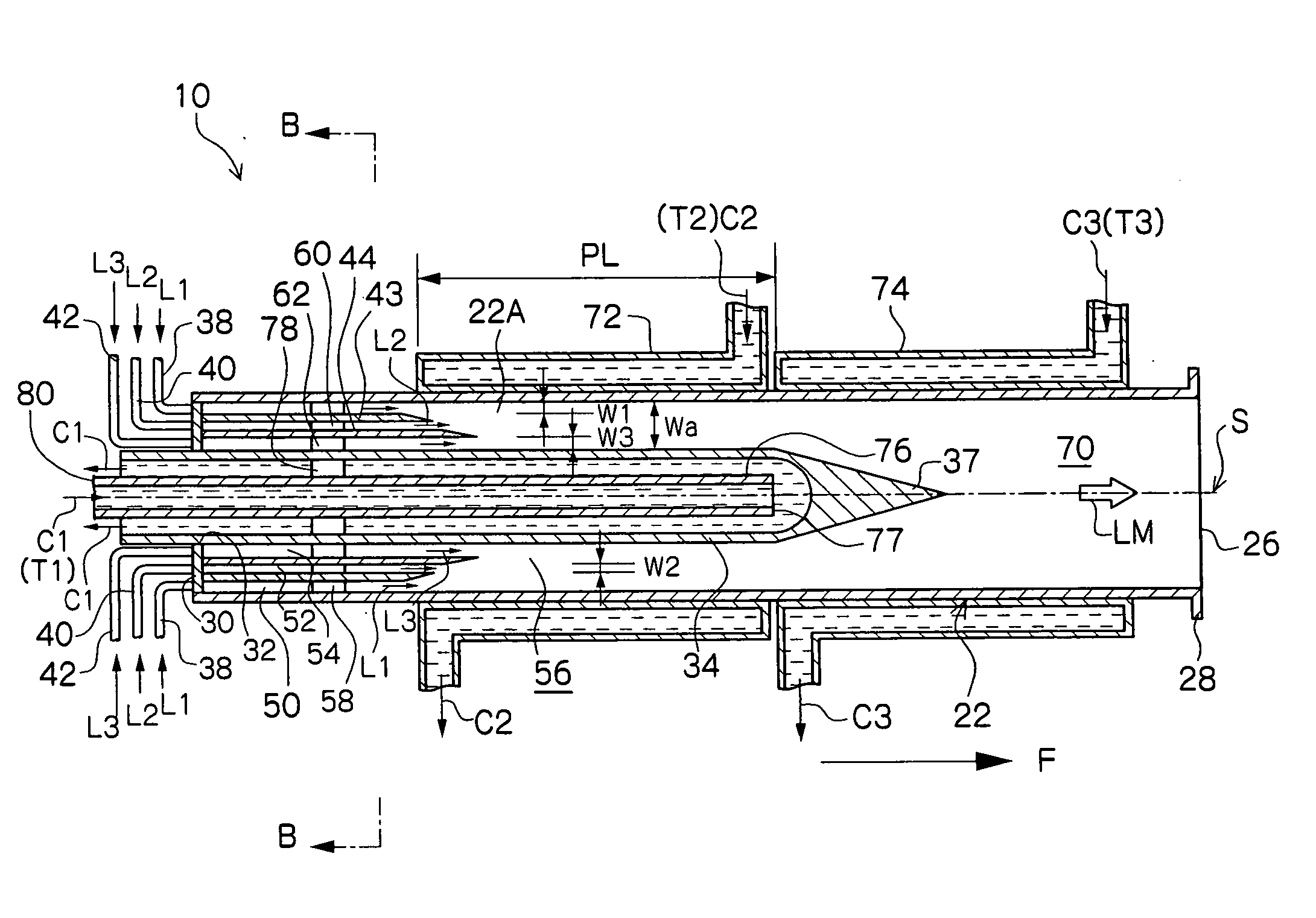
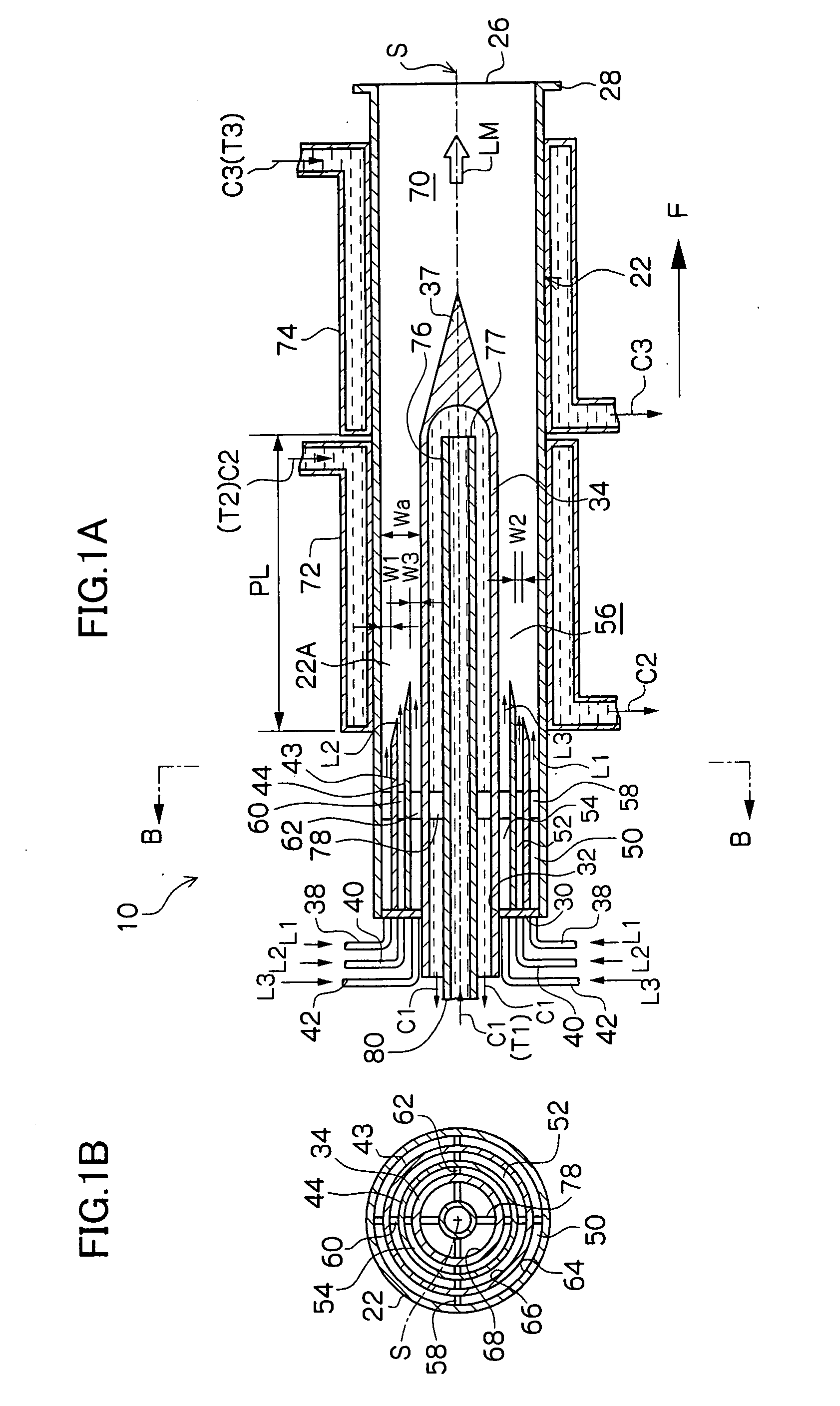
[0074] In this example, by use of a microreactor provided with four fluid supply routes which are formed as a multicylindrical structure having a co-axis, a reaction which involves the generation of fine particles silver chloride (AgCl) was caused to occur. Among four fluid supply routes, the innermost fluid supply route which comes into contact with the inner peripheral wall surface and outer peripheral wall surface of the reaction channel 56 and the outermost fluid supply route were each supplied with distilled water as a fluid not participating in the reaction, the second fluid supply route from the inside was supplied with a silver nitrate fluid (AgNO3), and the third fluid supply route from the inside was supplied with a sodium chloride fluid (NaCl). The opening width of the reaction channel 56 was 225 μm.
[0075] In the experiment, 0.05 mol / l of silver nitrate fluid and 0.05 mol / l of sodium chloride fluid were used, and each fluid was caused to contain 0.06 wt % low molecular w...
example 2
Example of a Reaction Using Fluorine Gas
[0081] In this example of the present invention, a fluorination reaction was caused to occur by use of a stainless steel microreactor as shown in FIG. 6, which is provided with four fluid supply routes formed as a multicylindrical structure having a co-axis (opening width of the reaction channel 56: 225 μm).
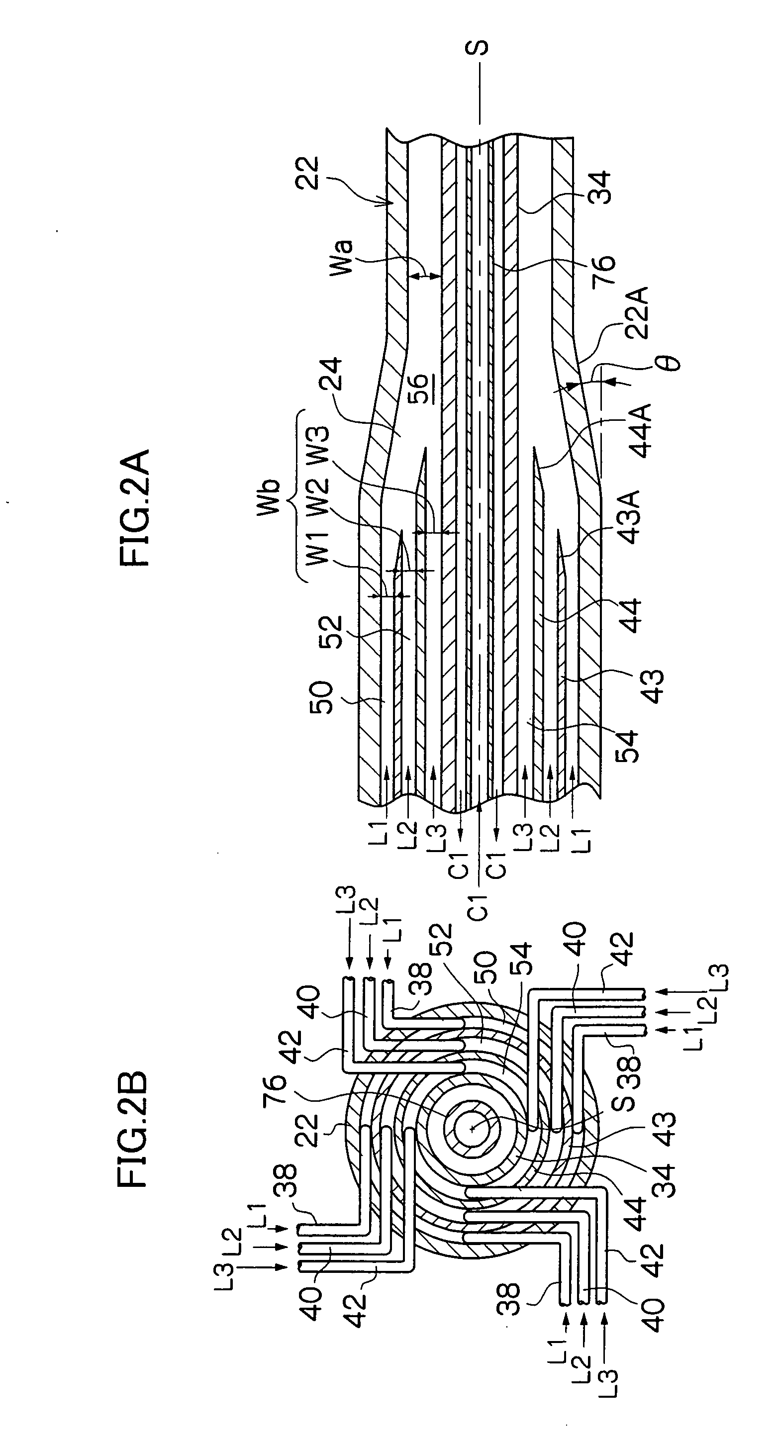
[0082] A cooling medium at −20° C. was circulated as the heat medium C1 shown in FIGS. 2A and 2B in order to control the reaction temperature, and perfluorohexane which is a solvent not participating in the reaction was caused to flow as the fluid L1 of FIG. 6. Next, 10 vol. % fluorine gas in nitrogen was caused to flow (10 ml / minute) as the fluid L2, and ethyl acetoacetate diluted with F-113 (1,1,2-richloro-trifluoroethane) (concentration: 10 wt. %) was caused to flow as the fluid L3 at a flow rate of 5 ml / h.
[0083] When a reaction liquid thus obtained was analyzed by use of high-speed liquid chromatography, it was found that 2-ethyl flu...
example 3
Example of Synthesis of Organic Pigment
[0085] In this example of the present invention, a reaction to synthesize an organic pigment of the following reaction formula was caused to occur by use of a stainless steel microreactor as shown in FIG. 8, which is provided with six fluid supply routes formed as a multicylindrical structure having a co-axis (opening width of the reaction channel 56: 300 μm).
[0086] Silicon oil heated to 180° C. was circulated as the heat medium C1 shown in FIGS. 1A and 1B in order to control the reaction temperature, and 1,2-dichlorobenzene which is a solvent at 80° C. was caused to flow as the fluid L1 of FIG. 8. Next, as the fluid L2 of FIG. 8, a solution obtained by causing 37.9 g (0.1 mol) of the above compound (A) to be suspended in 300 ml of 1,2-dichlorobenzene at 80° C. was dissolved in 300 ml of 1,2-dichlorobenzene and heated to 80° C., and this solution was caused to flow each time at a flow rate of 6 ml / minute by use of a piston pump.
[0087] When ...
PUM
| Property | Measurement | Unit |
|---|---|---|
| Width | aaaaa | aaaaa |
| Width | aaaaa | aaaaa |
| Temperature | aaaaa | aaaaa |
Abstract
Description
Claims
Application Information
 - R&D
- Intellectual Property
- Life Sciences
- Materials
- Tech Scout
- Unparalleled Data Quality
- Higher Quality Content
- 60% Fewer Hallucinations
Browse by: Latest US Patents, China's latest patents, Technical Efficacy Thesaurus, Application Domain, Technology Topic, Popular Technical Reports.
© 2025 PatSnap. All rights reserved.Legal|Privacy policy|Modern Slavery Act Transparency Statement|Sitemap|About US| Contact US: help@patsnap.com


